73
HELIX™ Manual
(P/N 26291)
Chapter 4: System Installation
Rev A (February 2018)
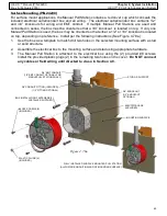
HELIX™ PCU
Fire Suppression System
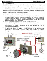
CONDUIT
(OPTIONAL)
ELECTRIC GAS
VALVE
CONDUIT
(OPTIONAL)
JUNCTION BOX
(AS REQUIRED)
12 VDC WIRING (14
-
26 AWG)
STRIKE CONTROL
UNIT
RELAY
MODULE
(P/N 24695)
GROUND LUG
A/C LINE
1
2
3
1 2 3 4
A/C NEUTRAL
GAS VALVE NEUTRAL
GAS VALVE LOAD
+12 VDC
GAS NC
RELAY 2
RELAY 3
RELAY 3*
RELAY 2*
NC
C
NO
NC
C
NO
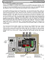
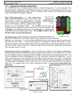
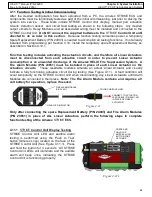
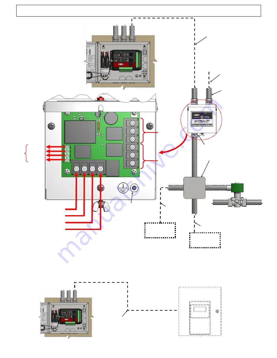
Figure 4.8.5a
A/C IN
T
O
S
T
R
IK
E
CONT
R
OL
UN
IT
OPTIONAL A/C
DEVICE
OPTIONAL A/C
DEVICE
RELAY #3 WIRING (12
-
22 AWG)
RELAY #2
WIRING
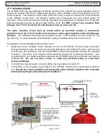
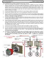
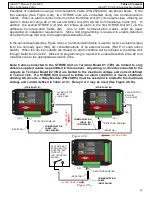
If an Auxiliary FACP is used, the STRIKE
Control Unit features additional alarm and fault outputs for
connection to an auxiliary fire alarm control panel (FACP). An EOL may also be installed on the
STRIKE
Control Unit. Connect and route wiring from the FACP to and into the STRIKE
Control Unit
enclosure using 16
-
24 AWG wiring (See Figure 4.8.5b). Termination of wiring to the STRIKE
Control Unit is shown in Section 4.9.
STRIKE CONTROL
UNIT
FACP CIRCUIT WIRING
(16
-
24 AWG)
AUXILIARY FACP
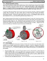
Figure 4.8.5b
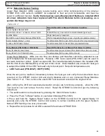
* Normally Open (N/O) &
COM contacts on Relay
2 or 3 may be used for
Communication Cable
(P/N 25264–XX)
connection for alarm
indication to an
additional STRIKE Unit
or external FACP. See
Figures 3.6.1c/d.

