74
HELIX™ Manual
(P/N 26291)
Chapter 4: System Installation
Rev A (February 2018)
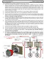
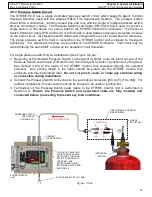
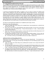
HELIX™ PCU
Fire Suppression System
4.9
STRIKE
Control Unit Wiring & Termination
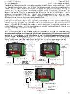
Following the installation of all field wiring to and into the STRIKE Control Unit enclosure, each
individual circuit must be terminated to the provided terminal strips on the STRIKE Control Unit. An
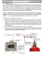
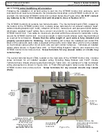
example of a terminated STRIKE Control Unit is shown below (See Figure 4.9a).
Do NOT connect
any batteries to the
STRIKE
Control Unit until directed to do so in Section 4.11.1.
The STRIKE Control Unit contains two terminal boards. The first terminal board (TB1), located on
the bottom of the STRIKE Control Unit, contains screw terminals for all Amerex supplied “Lead”
cables including detection (#1 & #2), actuation (#1 & #2), manual pull, and pressure switch cables.
All Amerex supplied “Lead” cables have a blunt cut end with no connector for termination on the
STRIKE Control Unit. Two cable tie mounts are provided within the enclosure for cable/wire routing
around the STRIKE Control Unit. Any excess length or slack in each Amerex cable may be trimmed
as required for termination.
Ensure that the entire length of each cable is fully installed and
properly secured prior to trimming.
Since trimming will remove the installed color coded P/N
label on the cable end, each cable is supplied with an extra color coded label, which can be installed
on the trimmed cable end for circuit color code and part number reference. Terminate all installed
cables where shown in Figure/Table 4.9b. A “Field Wiring Diagram” label is also located on the
STRIKE Control Unit enclosure door.
Screw terminals for any unused cables or circuits may
remain empty.
The second terminal board (TB2), located on the right side of the STRIKE Control Unit, contains
screw terminals for all installer supplied wiring including Relay Module and FACP circuits.
Terminate these circuits where needed according to Table 4.9c. An example of a fully terminated
wiring arrangement is shown in Figure 4.9c. A “Field Wiring Diagram” label is also located on the
STRIKE Control Unit enclosure door.
Screw terminals for any unused circuits may remain
empty.
CONDUIT
(AS REQUIRED)
CABLE TIE
MOUNT
LOCATIONS
TERMINAL STRIP #1 (TB1)
(AMEREX SUPPLIED CABLES):
PRESSURE SWITCH
DETECTION (#1 & #2)
MANUAL PULL STATION
ACTUATION (#1 & #2)
SEE FIGURE /TABLE 4.9b
FIELD
WIRING
DIAGRAM
LABEL
TERMINAL STRIP #2 (TB2)
(INSTALLER SUPPLIED WIRING):
AUXILIARY FACP
RELAYS (#1, #2 & #3)
SEE FIGURE/TABLE 4.9c
COLOR CODED
P/N LABELS ON
CABLE ENDS
Figure 4.9a
TB1
TB2

