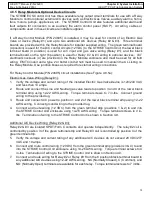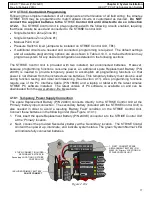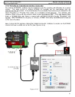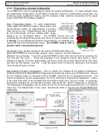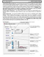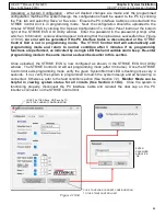
76
HELIX™ Manual
(P/N 26291)
Table of Contents
Rev A (February 2018)
HELIX™ PCU
Fire Suppression System
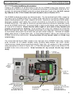
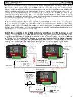
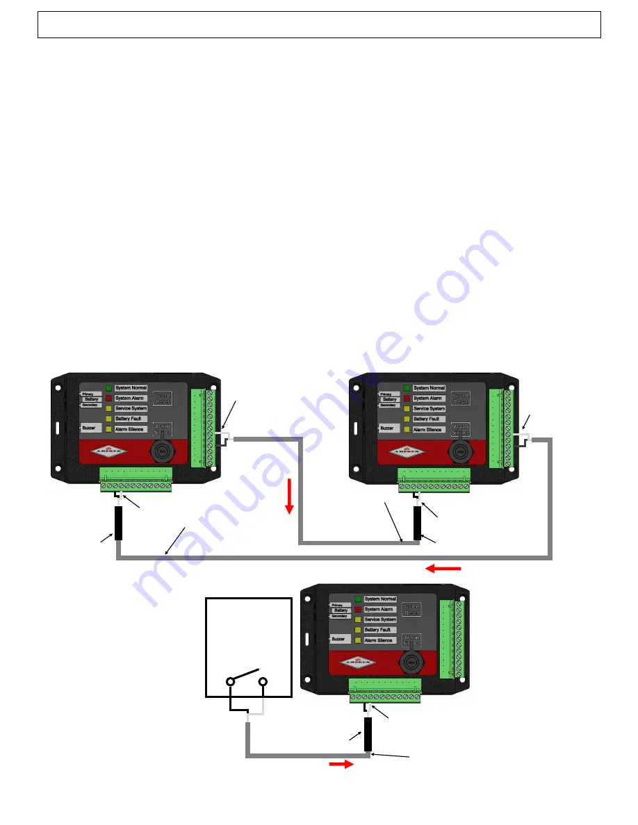
Examples of installations using a Communication Cable (P/N 25264
-
XX) are shown below. In the
first example (See Figure 4.9d), two STRIKE units are connected using two Communications
Cables. When an alarm condition occurs on the first Strike Unit (#1), its outputs close, initiating an
alarm in Detection Zone #2 of the second Strike Unit (#2) via the Communication Cable (#1). In
addition, the second STRIKE Unit (#2) can initiate an alarm in the first STRIKE Unit (#1) via the
additional Communication Cable (#2). One or both Communication Cables could be used,
depending on installation requirements. Strike Unit programming is required to enable Detection
Zone #2 and map that zone to the appropriate Actuation Zone.
In the second example (See Figure 4.9e), a Communication Cable is used to receive an alarm signal
from the normally open (NO) dry contacts/outputs of an external device (FACP or snap action
switch). When the device contacts are closed, an alarm condition will be initiated in the Strike Unit
through Detection Zone #2. Strike Unit programming is required to enable Detection Zone #2 and
map that zone to the appropriate Actuation Zone.
Note: Cables connected to the STRIKE Unit on Terminal Board #1 (TB1) are limited to only
Amerex supplied cables as permitted in this manual. Any wiring or circuits connected to the
outputs on Terminal Board #2 (TB2) are limited to the maximum voltage and current defined
in Table 2.7.2b. If a STRIKE Unit is used to initiate an alarm condition or device shutdown
utilizing AC circuits, a Relay Module (P/N 24695) must be used and is limited to the maximum
voltage and current defined in Table 2.13.1. Relay 2 or 3 may be used (See Figure 4.8.5a).
(STRIKE UNIT #1)
(TB1)
(TB2)
(STRIKE UNIT #2)
COMMUNICATION
CABLE (#1)
(P/N 25264
-
XX)
COMMUNICATION
CABLE (#2)
(P/N 25264
-
XX)
(RESISTOR)
(TB1)
(TB2)
(RESISTOR)
ALARM OUTPUT
#2 OR #3
(NO & COM)
ALARM OUTPUT
#2 OR #3
(NO & COM)
DETECTION ZONE (#2)
DETECTION ZONE (#2)
(A
LA
RM
S
IG
NA
L)
(ALARM SIGNAL)
Figure 4.9d
FACP OR SNAP
ACTION SWITCH
OUTPUTS, DRY
CONTACTS
(NO, CLOSED IN
ALARM)
(TB1)
COMMUNICATION
CABLE
(P/N 25264
-
XX)
(RESISTOR)
DETECTION ZONE (#2)
(ALARM SIGNAL)
Figure 4.9e


