85
HELIX™ Manual
(P/N 26291)
Chapter 4: System Installation
Rev A (February 2018)
HELIX™ PCU
Fire Suppression System
4.11.2 Detection Sensor Testing
Linear Heat Detector (LHD) sensors require testing upon initial commissioning of the Amerex
STRIKE ECS. LHD sensors CANNOT be subjected to their set point temperature and must be
tested in a different
manner.
Verify the temporary spare Replacement Battery is installed AND
all Linear Actuators have been replaced with Fire Alarm Modules before proceeding, as a
system discharge may occur.
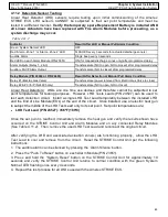
Linear Heat Detectors: LHDs are one time use devices and therefore cannot be subjected to set
point temperatures for testing purposes. However, LHD Tests Leads (P/N 24527) can be used
to
test each detection circuit. Install a single LHD Test Lead temporarily between the installed LHD
and the End of Line Module (EOL) at the end of the circuit. Once installed, use an electric heat gun
to subject the middle of the LHD Test Lead only to its set point. Set point temperatures are:
•
LHD Test Lead (P/N 24527): 356ºF (180ºC)
Once the set point is reached, immediately remove the heat gun and verify the results shown have
occurred on the STRIKE Control Unit and Alarm Modules and on any connected Relay Modules
(See Table 4.11.2). Then, remove the used LHD Test Lead and reconnect the original circuit.
After verifying the LHD and associated actuation zone(s) are functioning properly, allow the LHD
Test Lead to cool and remove from the circuit. Reset the STRIKE Control Unit per the following
instructions:
1. The audible alarm can be silenced by pressing the ‘Alarm Silence’ button.
2. Press the “Push To Reset” button on each Alarm Module (P/N 23651).
3.
Press and hold the “System Reset” button on the STRIKE Control Unit for approximately 10
seconds and verify the STRIKE Control Unit returns to normal condition with the green ’System
Normal’ LED flashing once every 4 seconds.
4.
Repeat this test process for all LHDs used with the Amerex STRIKE ECS
.
Indicator
Result After LHD or Manual Pull Alarm Condition
Green ‘System Normal’ LED
OFF
Red ‘Alarm– Zone 1’ or ‘Alarm– Zone 2’ LED
FLASHES every 3 seconds for actuated discharge zone(s)
Audible Alarm
Single beep every 3 seconds
Red LED on each Alarm Module (P/N 23651)
ON (for mapped discharge zones only) after programmed delay
Alarm Outputs (Relay 1, 2 & 3)
Transfers state (NC to open; NO to closed) after programmed delay
Auxiliary FACP Alarm Output
Transfers state (NO to closed) after programmed delay
Relay Module (P/N 24694 or P/N 24695)
Result After Detection or Manual Pull Alarm Condition
Relay #1 (Electric Gas Valve)
Transfers state (power removed from Electric Gas Valve to close)
Relay #2 & #3 (for P/N 24695 only)
Transfers state (NC to open; NO to closed)
Table 4.11.2


