86
HELIX™ Manual
(P/N 26291)
Chapter 4: System Installation
Rev A (February 2018)
HELIX™ PCU
Fire Suppression System
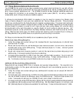
4.11.3 Manual Pull Station Testing
All Manual Pull Stations require
function testing upon initial commissioning of the Amerex STRIKE
ECS. Each station must be manually pulled to ensure that a system alarm condition and actuation
of the programmed discharge zone(s) will occur.
Verify the temporary spare Replacement
Battery is installed AND all Linear Actuators have been replaced with Fire Alarm Modules
before proceeding, as an Amerex HELIX Fire Suppression System discharge may occur.
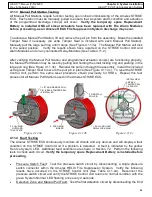
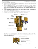
To activate a Manual Pull Station, lift and remove the pull pin from the assembly. Break the installed
Tamper Seal if necessary (an extra Tamper Seal is included with each Manual Pull Station).
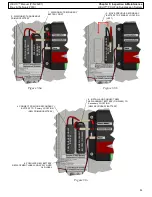
Manually pull the large pull ring until it stops (See Figure 4.11.3a). The Manual Pull Station will lock
in the pulled position. Verify the results shown have occurred on the STRIKE Control Unit and
Alarm Modules and on any connected Relay Modules (See Table 4.11.2).
After verifying the Manual Pull Station and programmed actuation zone(s) are functioning properly,
the Manual Pull Station may be reset by pulling and holding the small locking ring and pushing in the
large pull ring (See Figure 4.11.3b). Reinstall the pull pin through the assembly. Install the included
extra green Tamper Seal to secure the pull pin in place (See Figure 4.11.3c). To reset the STRIKE
Control Unit, perform the same reset procedure shown previously for SHDs. Repeat this test
process for all Manual Pull Stations used in the Amerex STRIKE ECS.
Figure 4.11.3b
1. LIFT AND REMOVE PULL
PIN. BREAK TAMPER SEAL
IF INSTALLED
2. PULL RING
OUTWARD
TO ACTIVATE
3. REINSTALL
PULL PIN
2. PUSH RING
INWARD
1. PULL AND HOLD
SMALL LOCK RING
INSTALL NEW
AMEREX
TAMPER SEAL
AS SHOWN
Figure 4.11.3c
Figure 4.11.3a
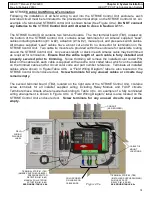
4.11.4 Fault Testing
The
Amerex STRIKE ECS continuously monitors all circuits and any devices and will display a fault
condition on the STRIKE Control Unit if a problem is detected. A fault is indicated by the yellow
‘Service System’ LED. Additional fault conditions are shown in Section 7.2. Perform the following
tests to check each circuit.
Verify the temporary spare Replacement Battery is installed before
proceeding.
•
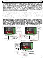
Pressure Switch Fault: Test the pressure switch circuit by disconnecting a single pressure
switch connector within the Amerex HELIX Fire Suppression System. Verify the following
results have occurred on the STRIKE Control Unit (See Table 4.11.4a). Reconnect the
pressure switch circuit and verify the STRIKE Control Unit returns to normal condition with the
green ’System Normal’ LED flashing once every
4 seconds.
•
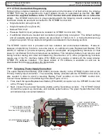
Detection Zone and Manual Pull Fault: Test the first detection circuit by disconnecting the End

