87
HELIX™ Manual
(P/N 26291)
Chapter 4: System Installation
Rev A (February 2018)
HELIX™ PCU
Fire Suppression System
4.12 Placing the System in Service
4.12.1 Placing the Suppression System in Service
Once the installation instructions from the previous sections are complete, perform the following
steps in order to place the Amerex HELIX Fire Suppression System into working service:
•
Connect any Agent Distribution Networks to Agent Cylinder(s) and Nozzles.
•
Connect any Pneumatic Actuation Network(s).
•
Locate and check all Agent Cylinder Pressure Switches.
•
Locate any other electrical components used in the system including any Linear Actuator (P/N
20500
-
R) used in actuators or control heads and any 50 psi Pressure Switches (P/N 22573
-
R or
23850
-
R) used in a Pneumatic Actuation Network. Each component will be connected to the
PCU’s STRIKE ECS System.
•
Make final documentation confirming all details of the complete installation compared to the
PCU analysis from Chapter 3.
•
Perform the monthly inspection as described in Chapter 5.
•
NFPA 12 requires blowing out the discharge lines and verifying the pneumatic actuation circuit
will function.
4.12.2 Placing the STRIKE ECS System into Service
Following the completion of all function testing and initial commissioning, the Amerex STRIKE ECS
may be placed into service by performing the following steps:
•
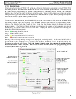
Battery Fault: Test the battery fault by disconnecting the single ’Secondary’ battery connector
from the STRIKE Control Unit. Verify the following results have occurred on the STRIKE
Control Unit (See Table 4.11.4b). Reconnect the battery and verify the STRIKE Control Unit
returns to normal condition with the green ’System Normal’ LED flashing once every
4 seconds.
Indicator
Result After Circuit Disconnect
Green ‘System Normal’ LED
OFF
Yellow ‘Battery Fault’ LED
FLASHES every 4 seconds (after approximately 30
-
60 seconds)
Audible Alarm
Single beep approximately every 10 minutes
Auxiliary FACP Fault Output
Transfers state (NC to open) after programmed delay
Table 4.11.4b
Indicator
Result After Circuit Disconnect
Green ‘System Normal’ LED
OFF
Yellow ‘Service System’ LED
FLASHES every 4 seconds
Audible Alarm
Single beep every 4 seconds
Auxiliary FACP Fault Output
Transfers state (NC to open) after programmed delay
Table 4.11.4a
of Line Module (EOL) at the end of the circuit. Verify the following results have occurred on the
STRIKE Control Unit (See Table 4.11.4a). Reconnect the EOL and verify the STRIKE Control
Unit returns to normal condition with the green ’System Normal’ LED flashing once every 4
seconds. Repeat this procedure for the second detection circuit (if enabled) and the manual
pull circuit.
•
Discharge Zone (Actuation) Fault: Test the first actuation circuit by disconnecting the Linear
Actuator at the end of the circuit. Verify the following results have occurred on the STRIKE
Control Unit (See Table 4.11.4a). Reconnect the Linear Actuator and verify the STRIKE
Control Unit returns to normal condition with the green ’System Normal’ LED flashing once
every 4 seconds. Repeat this procedure for the second actuation circuit (if enabled).


