92
HELIX™ Manual
(P/N 26291)
Chapter 5: Inspection & Maintenance
Rev A (February 2018)
HELIX™ PCU
Fire Suppression System
5.5 (12) Twelve Year Maintenance: AUTHORIZED AMEREX TECHNICIAN
•
Perform (6) six year maintenance.
•
The Agent Cylinder and all hose assemblies must be hydrostatically tested at a minimum of
every 12 years in accordance with CGA Pamphlet C
-
6, NFPA 17, and DOT requirements. Test
pressure can be found either in the latest version of this manual (See Section 2.1), or on the
Agent Cylinder nameplate. Date of Agent Cylinder manufacture is stamped on the Agent
Cylinder dome.
Hydrostatic testing may only be done by individuals certified to perform
hydrostatic testing by those having jurisdiction in the particular area.
When hydrostatically
testing Agent Cylinders, replace Agent Cylinder Valve with the Hydrotest Adapter (P/N 05152).
Connect a pressurization hose or network rated at or above the test pressure to the Hydrotest
Adapter (See Section 6.1.2).
5.6 Battery Replacement Procedure: AUTHORIZED AMEREX SERVICE REPRESENTATIVE
The
internal Lithium
-
Thionyl Chloride (LI
-
SOC12) batteries installed in the STRIKE Control Unit
enclosure will require periodic replacement. Rather than replace both batteries at the same time,
this replacement procedure involves removing the current ‘Primary’ battery and replacing it with the
current ‘Secondary’ battery, and a new Replacement Battery (P/N 24903) is installed at the
‘Secondary’ location. Before performing this replacement procedure or performing system
maintenance, follow the procedure for servicing the system. The battery replacement procedure
shall also be performed following these events:
Primary Battery is over 6 months old
Battery Replacement Label is missing
A trouble (fault) condition occurs
An alarm condition event occurs
Low battery indicator (‘Battery Fault’) on STRIKE Control Unit is illuminated
Label information is not legible
Battery Replacement Procedure:
1.
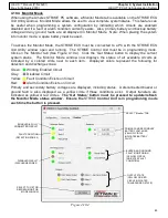
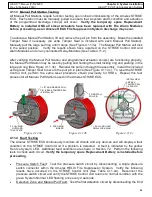
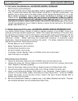
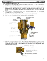
Unplug the ‘Secondary’ battery from the STRIKE Control Unit (See Figure 5.6a).
2.
Unplug and remove the ‘Primary’ Battery from the STRIKE Control Unit enclosure (See Figure
5.6a). Dispose of this battery properly.
3.
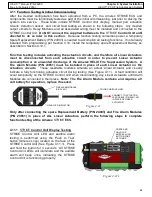
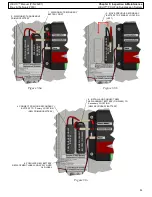
Move the ‘Secondary’ battery to the ‘Primary’ bracket location on left (See Figure 5.6b).
4.
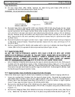
Connect the previous secondary battery (left) to the ‘Primary’ battery connection port.
5.
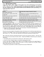
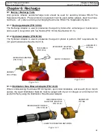
Install a new Replacement Battery (P/N 24903) in the ‘Secondary’ bracket location on right.
Connect to the ‘Secondary’ battery connection port (See Figure 5.6c). Verify the STRIKE
Control Unit powers up and resumes normal condition with green ’System
Normal’ LED is
flashing once every 4 seconds.
6.
Each new Replacement Battery is supplied with a new Battery Replacement Label. Populate
the new label and place over the old label (See Figure 5.6c).

