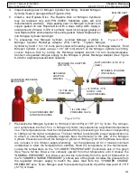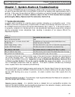
96
HELIX™
Manual (P/N 26291)
Chapter 6: Recharge
Rev A (February 2018)
HELIX™
PCU Fire Suppression System
6.2 Recharge Instructions
WARNING! BEFORE ATTEMPTING ANY RECHARGE PROCEDURES, FIRST CONFIRM THE
REASON FOR THE DISCHARGE AND CORRECT ANY CONDITIONS THAT CAUSED THE
SYSTEM TO DISCHARGE. IF RECHARGE CANNOT BE ACCOMPLISHED IMMEDIATELY, DO
NOT LEAVE THE SYSTEM INCAPACITATED FOR ANY REASON WITHOUT GIVING WRITTEN
NOTIFICATION TO THE OWNER, OWNER’S AGENT, AND OR LOCAL AHJ. ALSO,
DOCUMENT THE INCIDENT IN THE PERMANENT JOB FILE BEFORE LEAVING THE SCENE.
ANY SYSTEM COMPONENTS SUBJECTED TO FIRE OR OVERHEAT CONDITIONS MUST BE
REPLACED, INCLUDING, BUT NOT LIMITED TO CYLINDERS, BRACKETS, DETECTORS,
DETECTOR CIRCUITS, NOZZLES, AND AGENT DISTRIBUTION NETWORKS AND PNEUMATIC
ACTUATION NETWORKS.
WARNING! ENSURE THAT ALL PRESSURE HAS BEEN RELIEVED FROM AGENT CYLINDER
BEFORE PROCEEDING. CONSULT SAFETY DATA SHEET (SDS) FOUND ON AMEREX
WEBSITE WWW.AMEREX
-
FIRE.COM.
Remove all sources of power that are involved with the fire suppression system. Immediately clean
all surfaces contacted by Dry Chemical Agent. Methods for cleaning:
1.
If the Dry Chemical Agent has not been heated to its melting point, it may be swept and
vacuumed from all surfaces it has contacted.
2.
Use shop air to blow residual chemical away from surfaces. Note: Amerex Dry Chemical Agent
is considered a nuisance dust and is non
-
toxic. See SDS on Amerex website at www.amerex
-
fire.com.
3.
Additionally, power spraying or steam cleaning can be done to remove any additional Dry
Chemical Agent. Mild soapy water can sometimes be utilized. Contact equipment owner/
operator for permission to use water prior to taking this step.
6.2.1 Agent Cylinder Control Head Removal & Cleaning
Reference the appropriate subsection for control head removal, disassembly, cleaning and
reassembly instructions.
For Systems Using Pneumatic Control Head (P/N 10147
-
R)
For systems using a Pneumatic Control Head (P/N 10147
-
R) along with a Pneumatic Actuation
Network, perform the following steps. The Control Head must be disassembled, cleaned, and
reassembled after each use.
Control Head Removal (See Figure 4.
3.2a & 4.3.2b):
1.
Relieve any residual nitrogen pressure in the Pneumatic Actuation Network by slowly unseating
the Vent Check (P/N 10173
-
R). Remove Vent Check.
2.
Remove Pneumatic Actuation Network at Control Head inlet/exit.
3.
Carefully remove Pneumatic Control Head from Agent Cylinder Valve by removing (2) 5/16”
-
18
bolts.
4.
Install Shipping Plate (P/N 10099) in place of Pneumatic Control Head (See Figure 2.1a)
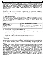
Control Head Disassembly (See Figure 6.2.1a):
5.
Use retaining ring pliers to remove the Retaining Ring (P/N 10149) (Note: Always use eye
protection when doing this step).
6.
Remove the Safety Lock Washer (P/N 17637) and Pneumatic Piston Assembly (P/N 17635) with
O
-
ring (P/N 10148).

