background image

10 

Service Department: 888.270.6879 


“WARNING” 


LOCK OUT POWER before performing any cleaning, oiling, maintenance, or trouble shooting. 

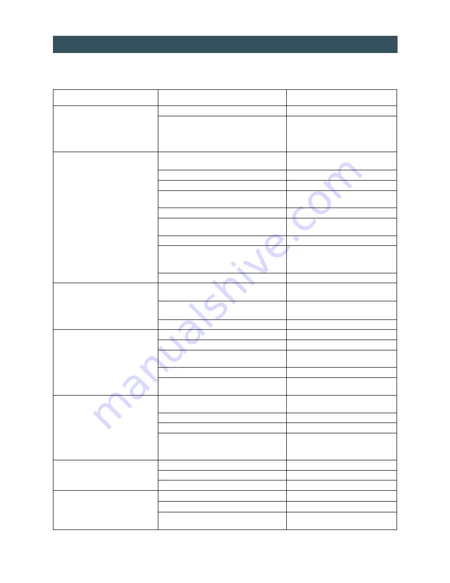
TROUBLE SHOOTING 

PROBLEM 

POSSIBLE CAUSE 

REMEDY 

Defective STOP button. 

Check continuity (N.C.) If bad, replace. 

Machine will not turn off using STOP 
buttons.  

Contacts burned together in reversing contactor. 

Check each leg of forward side of 
contactor for continuity. There should be 
no continuity. If there is, consult factory 
for replacement part. 

Machine will not run in forward or 
reverse. 

If power light is illuminated, proceed to possible 
cause seven. 


1)    No power. 

Check power supply. 

2)    Key switch off. 

Turn on. 

3)    Fuse blown in disconnect. 

Remove each fuse and check for 
continuity. If bad, replace. 

4)    Overload tripped in panel. 

Reset. 

5)    Control transformer fuse blown. 

Remove fuse and check for continuity. If 
bad, replace. 

6)    Stop button stuck “in”. 

Check buttons. 

7)    Loose wire in panel. 

Check terminal strip for disconnected or 
loose wires. Reconnect and tighten loose 
wires to proper location on strip. 

8)    Defective contact block on stop button. 

Check block for continuity. If bad, replace. 

Motor hums or buzzes, but will not turn 
in either forward or reverse. 

One leg of the 3 phase power is dead (single 
phasing). 

Remove each fuse. Check for continuity in 
the power supply and disconnect. 

Contacts burned in contactor and not making a 
connection on one leg. 

Consult factory for replacement contactor. 

Defective or damaged motor. 

Consult factory for replacement motor. 

Overload tripping. 

Low voltage. 

Check voltage. 

Current relay set too high. 

See instructions on previous page. 

Motor overheating. 

Check motor cooling fan for objects 
obstructing air flow. 

Cutter-head is dirty or not lubricated  

Clean and lube. 

Defective or damaged motor. 

Conduct amperage test.  Consult factory 
for replacement motor. 

Machine will not run in forward but will 
run in reverse. 

Defective forward button. 

Check contact block for continuity.  If bad, 
replace. 

Disconnected wire on forward button. 

Check and reconnect. 

Disconnected wire on current relay. 

Check and reconnect. 

Current relay stuck open. 

Clean relay. Free up center spool. Check 
continuity. If bad, consult factory for 
replacement relay. 

Machine will not run in reverse but will 
run in forward. 

Defective reverse button. 

Check for continuity.  If bad, replace. 

Disconnected wire on reverse button. 

Check and reconnect. 

Defective coil in reverse side of contactor. 

Consult factory for replacement coil. 

Shredding capacity is low. 

Cutter-head not lubricated. 

Clean and oil cutter-head. 

Low voltage. 

Check voltage at power supply. 

Current relay set too low. 

See instructions on previous page. 

Summary of Contents for AMS-150-SSD

Page 1: ...S 300 SSD OWNER S MANUAL SERIES 1 HARD DRIVE NOTICE The information contained within this manual is correct at time of printing but due to the continuing development of products changes in specifications are inevitable Ameri Shred reserves the right to implement such changes without prior notice ...

Page 2: ... WARNING 8 CLEARING A JAM 9 SHUT DOWN PROCEDURE 9 CURRENT RELAY ADJUSTMENT 9 TROUBLESHOOTING 10 MAINTENANCE 11 12 MAINTENANCE CHECKLISTS 13 16 CONVEYOR BELT ADJUSTMENT 17 PARTS LISTS CUTTER ASSEMBLY HD SSD MODELS 18 19 CUTTER ASSEMBLY HD MODELS 20 21 CUTTER ASSEMBLY SSD MODELS 22 OUTPUT CONVEYOR 23 ELECTRICAL DIAGRAMS 1 5 HP MODELS 24 29 ELECTRICAL DIAGRAMS 3 HP MODELS 30 33 TABLE OF CONTENTS ...

Page 3: ...he conveyor to the shredder NOTE Series 1 Hard Drive Shredders are top heavy which results in a tipping hazard Always use care when moving the shredder and stay clear of it in the event of a tip The shredder is too heavy to stop mid way and it can cause serious injury Give wide berth if it tips over and ensure that it will not come in contact with any body parts The potential for tipping is increa...

Page 4: ...ts as shown on nameplate Plug in power cable Clear all personnel from machine area Ensure machine is clean and no tools rags or debris have been left on or near cutters or drive mechanism Turn building service drop power on Check voltage at installed receptacle Ensure area is clear Turn key switch to the ON position Jog reverse Check for proper motor rotation If running in reverse unplug power cab...

Page 5: ...ime NEVER operate this or any other machine while under the influence of drugs alcohol or medications NEVER wear loose fitting clothing ties or jewelry while in the vicinity of this shredder NEVER allow long hair to be worn in the vicinity of the machine without use of a protective hair net NEVER place any part of your body in or on any part of this machine while in operation NEVER allow tools rag...

Page 6: ...partment 888 270 6879 DUAL INFEED SLOTS HD SSD MODELS SSD SOLID STATE DRIVES SHREDDER OPERATION CONTROL PANEL Key Switch Power Light Forward Reverse E Stop INFEED SLOT OPTIONAL OUTPUT CONVEYOR HDD HARD DISK DRIVES ...

Page 7: ...uency at which they feed the drives The operator will soon be able to judge the efficiency of the operation and feed material accordingly It is nearly inevitable that during this learning process the machine will jam A jam condition will automatically turn off the machine just as if the operator had depressed the STOP button This is normal PRE START UP PROCEDURE HD models have 1 5 or 3 4 wide cutt...

Page 8: ...ROTATIONAL HARD DRIVES ARE CONSTRUCTED IN A WAY THAT MAY WARRANT EXTRA ATTENTION Listed below are some 1 Hard Drives that may cause jamming Drives that have thick steel parts These steel parts may need to be removed prior to shredding in order to prevent jamming REMINDER Use HDD side only on HD SSD models SERVER DRIVE JAM WARNING Drives with multiple steel plates covering platters These plates may...

Page 9: ...include but are not limited to repeated jamming an inappropriate sound smell shaking etc This can result in shredder damage and void the warranty Instead stop shredding immediately and set the media aside for a different means of destruction CLEARING A JAM Allow input chute and output conveyor if provided to clear all material before shut down Depress red STOP pushbutton Remove power cable from re...

Page 10: ...dead single phasing Remove each fuse Check for continuity in the power supply and disconnect Contacts burned in contactor and not making a connection on one leg Consult factory for replacement contactor Defective or damaged motor Consult factory for replacement motor Overload tripping Low voltage Check voltage Current relay set too high See instructions on previous page Motor overheating Check mot...

Page 11: ...0 hours of operation Repeat steps from daily lubrication Remove guards Apply open gear lube or grease to spur gears Replace all guards Monthly lubrication After each 160 hours of operation Repeat steps from weekly lubrication Remove guards Check reducer oil level DO NOT OVERFILL Grease output conveyor bearings using a multipurpose lithium based grease Replace all guards Annual lubrication After 20...

Page 12: ...LUBE SCHEDULE ITEM LUBE FREQUENCY TYPE LUBE Spur gears Weekly Open Gear Lube Aerosol Reducer Check weekly Gear Oil High Grade Petroleum Based Rust Oxidation Inhibited Drain and refill yearly 2500 hours Cutters Every 4 to 8 hours 10W 20W 30W Motor Oil Output conveyor pulley bearings Monthly Multipurpose Grease ...

Page 13: ...13 Service Department 888 270 6879 MAINTENANCE CHECKLIST DAILY ...

Page 14: ...14 Service Department 888 270 6879 MAINTENANCE CHECKLIST WEEKLY ...

Page 15: ...15 Service Department 888 270 6879 MAINTENANCE CHECKLIST MONTHLY ...

Page 16: ...16 Service Department 888 270 6879 MAINTENANCE CHECKLIST YEARLY ...

Page 17: ...Ensure all personnel are clear and that no tools are on machine or input chute Turn power on Run machine in forward Stop machine and turn power off Adjust alignment by tightening take up bolt on side of conveyor where belt is rubbing side frame Tighten only one quarter turn at a time Tighten jam nuts Replace all guards Turn power on Run machine in forward for five minutes If further alignment is r...

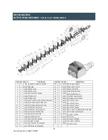
Page 18: ...SSD TIE BAR OUTSIDE SPACER DRIVE SIDE 27 5 34267 SSD CUTTER STYLE 1 9 4 34584 HD TIE BAR SPACER DRIVE SIDE 28 4 34268 SSD CUTTER STYLE 2 10 2 35483 HD TIE BAR SPACER IDLER SIDE 29 6 34269 SSD CUTTER STYLE 3 11 1 34463 SIDE PLATE DRIVE SIDE 30 2 34464 HD OUTER COMBER 12 1 34462 SIDE PLATE SPUR GEAR SIDE 31 4 34272 SSD OUTSIDE TIE BAR SPACERS IDLER SIDE 13 1 34582 END PLATE REDUCER SIDE 32 2 34275 S...

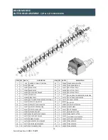
Page 19: ...ER 8 4 34586 SSD TIE BAR OUTSIDE SPACER DRIVE SIDE 27 13 34276 SSD SHAFT SPACER 9 1 34463 SIDE PLATE DRIVE SIDE 28 2 110016 SPUR GEAR 10 1 34462 SIDE PLATE SPUR GEAR SIDE 29 1 34887 DIVIDER SHAFT SPACER 11 1 34582 END PLATE REDUCER SIDE 30 3 344580 REAR COMBER 12 1 34581 END PLATE IDLER SIDE 31 4 34457 FRONT COMBER 13 1 34580 DIVIDER SIDE PLATE 32 3 33617 IDLER SHAFT CUTTER 14 1 34872 SPACER PASS ...

Page 20: ...BEARING BLOCK 12 2 33663 SPACER 3 1 N A REDUCER CONSULT FACTORY 13 2 33772 SIDE PLATE 4 1 33615 DRIVE SHAFT 14 1 33772 SIDE PLATE 5 2 33616 DRIVE SHAFT CUTTER 15 2 33625 END PLATE 6 1 33617 IDLE SHAFT CUTTER 16 2 110016 SPUR GEAR 7 2 33619 WEAR BLOCK 17 2 34464 WEAR BLOCK COMBER 8 1 33618 IDLER SHAFT 18 2 33740 COMBER WELDMENT 9 4 111907 BEARING 19 1 33739 COMBER WELDMENT 10 4 33620 COMBER TIE BAR...

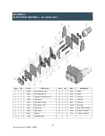
Page 21: ...2 1 33585 IDLE BEARING BLOCK 11 2 33619 75 WEAR BLOCK 3 1 N A REDUCER CONSULT FACTORY 12 3 33617 75 IDLE SHAFT CUTTER 4 1 33615 DRIVE SHAFT 13 4 33616 75 DRIVE SHAFT CUTTER 5 1 33618 IDLER SHAFT 14 5 33616 75 SHAFT HEX SPACER 6 4 111907 BEARING 15 2 33663 75 SHAFT HEX SPACER 7 2 33625 END PLATE 16 2 110016 SPUR GEAR 8 1 33772 SIDE PLATE 17 7 33925 COMBER WELDMENT 9 1 33772 SIDE PLATE OPTIONAL ...

Page 22: ...ER STYLE 2 4 1 33615 DRIVE SHAFT 16 4 34269 CUTTER STYLE 3 5 1 33618 IDLER SHAFT 17 13 34276 INSIDE SHAFT SPACER 6 4 111907 BEARING 18 30 34575 INSIDE TIE BAR SPACER 7 1 34449 CUTTERHEAD END PLATE REAR 19 7 34576 REAR COMBER 8 1 34448 CUTTERHEAD END PLATE FRONT 20 6 34577 FRONT COMBER 9 1 34462 SIDE PLATE SPUR GEAR SIDE 21 2 34513 OUTSIDE SHAFT SPACER 10 1 34463 SIDE PLATE DRIVE SIDE 22 2 34498 OU...

Page 23: ...YOR BED 23 1 33904 END GUARD 7 1 34861 BOTTOM GUARD 24 2 20254 PIVOT BRACKET 8 1 33909 FOOT CROSSMEMBER 25 2 15294 TAKE UP ANGLE 9 2 33910 FOOT CROSSMEMBER MOUNT 26 2 33906 LEG MOUNT BRACKET 10 2 34862 SIDE SLIDE HOLDER BRACKET 27 1 12047 DRIVE SHAFT 11 2 34863 ANGLED SIDE SLIDE 28 1 112046 DRIVE PULLEY 12 1 34864 VERTICAL END GUARD 29 1 112044 TAIL PULLEY 13 1 34865 CONVEYOR MOUNT BRACKET 30 1 11...

Page 24: ...24 Service Department 888 270 6879 ELECTRICAL DIAGRAM 1 5 HP MODELS 120V 1 PHASE ...

Page 25: ...25 Service Department 888 270 6879 ELECTRICAL DIAGRAM 1 5 HP MODELS 220V 1 PHASE ...

Page 26: ...26 Service Department 888 270 6879 ELECTRICAL DIAGRAM 1 5 HP MODELS 208V 3 PHASE ...

Page 27: ...27 Service Department 888 270 6879 ELECTRICAL DIAGRAM 1 5 HP MODELS 230V 3 PHASE ...

Page 28: ...1 104656 PLUG 460V 3PH 1 104223 BACKPLATE 1 104224 ENCLOSURE 12 X 14 X 8 MTR 1 104025 MOTOR 3 HP 230 460V CT 1 104629 CURRENT TRANSFORMER FU 2 2 111218 FUSE 1 2 AMP FU 1 1 111136 FUSE 2 AMP CR 1 104528 CURRENT RELAY OL 1 1 111264 OVERLOAD 4 6 AMPS TRANS 1 104623 TRANSFORMER MFR 1 111251 MOTOR STARTER 18 AMP PB 3 1 104440 FORWARD BUTTON PB 2 1 104441 REVERSE BUTTON PB 1 1 104449 STOP BUTTON PL 1 1 ...

Page 29: ...29 Service Department 888 270 6879 ELECTRICAL DIAGRAM 1 5 HP MODELS 575V 3 PHASE ...

Page 30: ...30 Service Department 888 270 6879 ELECTRICAL DIAGRAM 3 HP MODELS 208V 3 PHASE ...

Page 31: ...31 Service Department 888 270 6879 ELECTRICAL DIAGRAM 3 HP MODELS 230V 3 PHASE ...

Page 32: ...32 Service Department 888 270 6879 ELECTRICAL DIAGRAM 3 HP MODELS 460V 3 PHASE ...

Page 33: ...33 Service Department 888 270 6879 ELECTRICAL DIAGRAM 3 HP MODELS 575V 3 PHASE ...

Page 34: ...34 Service Department 888 270 6879 3490 US 23 N Alpena MI 49707 Toll Free 800 634 8981 Phone 989 358 6121 Fax 989 358 6122 info ameri shred com www ameri shred com ...

Reviews: