8
Ramp Assembly
Our standard ramp sizes are 2’, 3’, 4’, 5’, and 6’ sections. Ramps are available in 48” and 54” widths (clear width between
curbs). Consult manufacturer for custom widths beyond 54”.
All of the ramp sections are welded to meet a 1:12 pitch.
Items needed for assembly depending on location of section:
Ramp section, proper length supports, 14” inserts,
TT48, TPCOM, BPCOM, RHP, impact wrench, tape measure, level, 9/16” socket, 3/8” nut driver bit.
Existing Landing/Deck/Porch to Ramp
1. Determine the ramp height required for the location and choose the correct support length.
A ramp section that
comes directly from an existing landing will need (4) supports. Ensure there is 10” minimum of support tubing
extending above the support sockets. The guard rails will slide over the extended tubing.
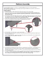
2. Screw the .75” bolts into the support sockets located laterally on each side and both the top and bottom of section.
3. Insert supports into each socket, set at approximate 1:12 height and lightly tighten bolts.
Always position supports
where the long end of the foot pad is facing the bottom (groove end) of the ramp section.
4. Position ramp section in final location with the “groove end” always at the bottom. Make necessary slope adjustments,
level horizontally, and firmly secure .75” bolts.
5. Use a TPCOM to secure ramp section to existing landing in the same manner as securing a platform.
Platform to Ramp/Ramp to Platform
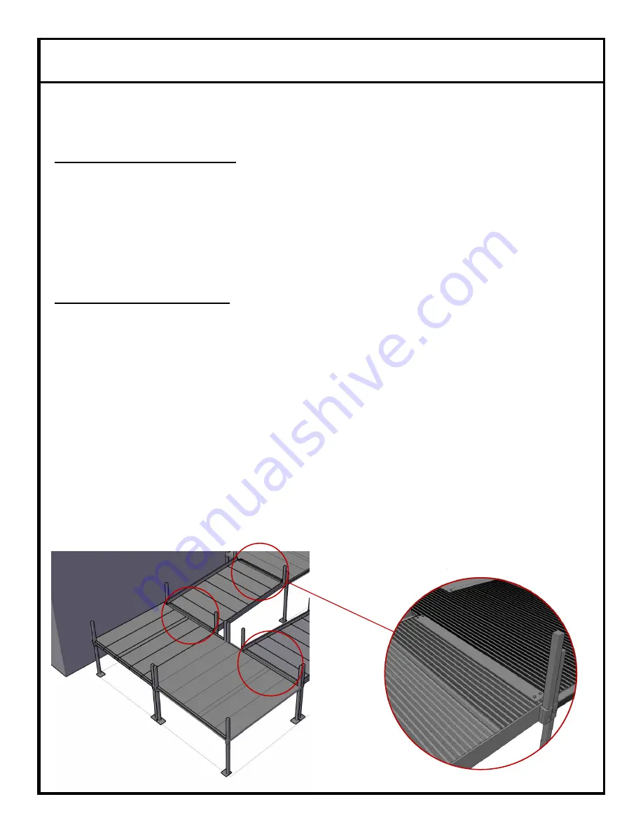
1. Assemble the ramp section in the same manner as described above. If using a “tongue and groove” connection with the
platform, the ramp section will need (2) supports and (2) inserts.
2. Secure (2) supports in the bottom ramp sockets (groove end) at the approximate height to meet a 1:12 slope and 14”
inserts into the top sockets (tongue end).
The bottom of the insert should be held flush with the bottom of the ramp
socket while securing.
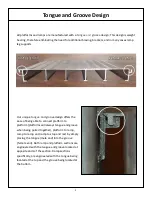
3. Place the “tongue” at the top of the ramp section into the “groove” of the platform.
The groove of the platform is
weight bearing and will support the weight of the top half of the ramp section.
4. Position top of ramp section where the outside edge of the ramp tongue and platform groove are flush.
The ramp
socket and corner platform socket should be aligned.
5. Make necessary 1:12 slope adjustments, level horizontally, and firmly secure .75” bolts.
6. Use (4) #14 x 1” Tek Screws to secure the ramp to the platform via BPCOM.
7. If the ramp section is exiting a platform on a non-groove side (standard side), the section is considered a supporting
section. A supporting section will need (2) supports in the top sockets and (2) supports in the bottom sockets. A BPCOM
will be used to secure the connection between the platform and ramp.
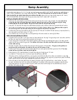
8. When entering onto the standard side (non tongue and groove side) of a platform from a ramp section, the ramp
“groove” should be flush with the surface of the platform. The bottom of the ramp section (groove end) will butt up
against the platform. The ramp socket and corner platform socket should be aligned. Use a BPCOM to secure the
platform to the ramp section.


