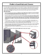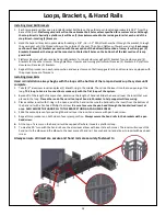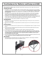
9
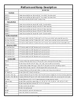
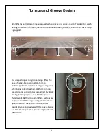
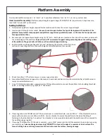
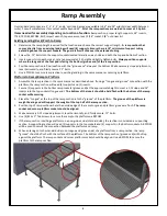
Ramp assembly figure page
Ramp Assembly
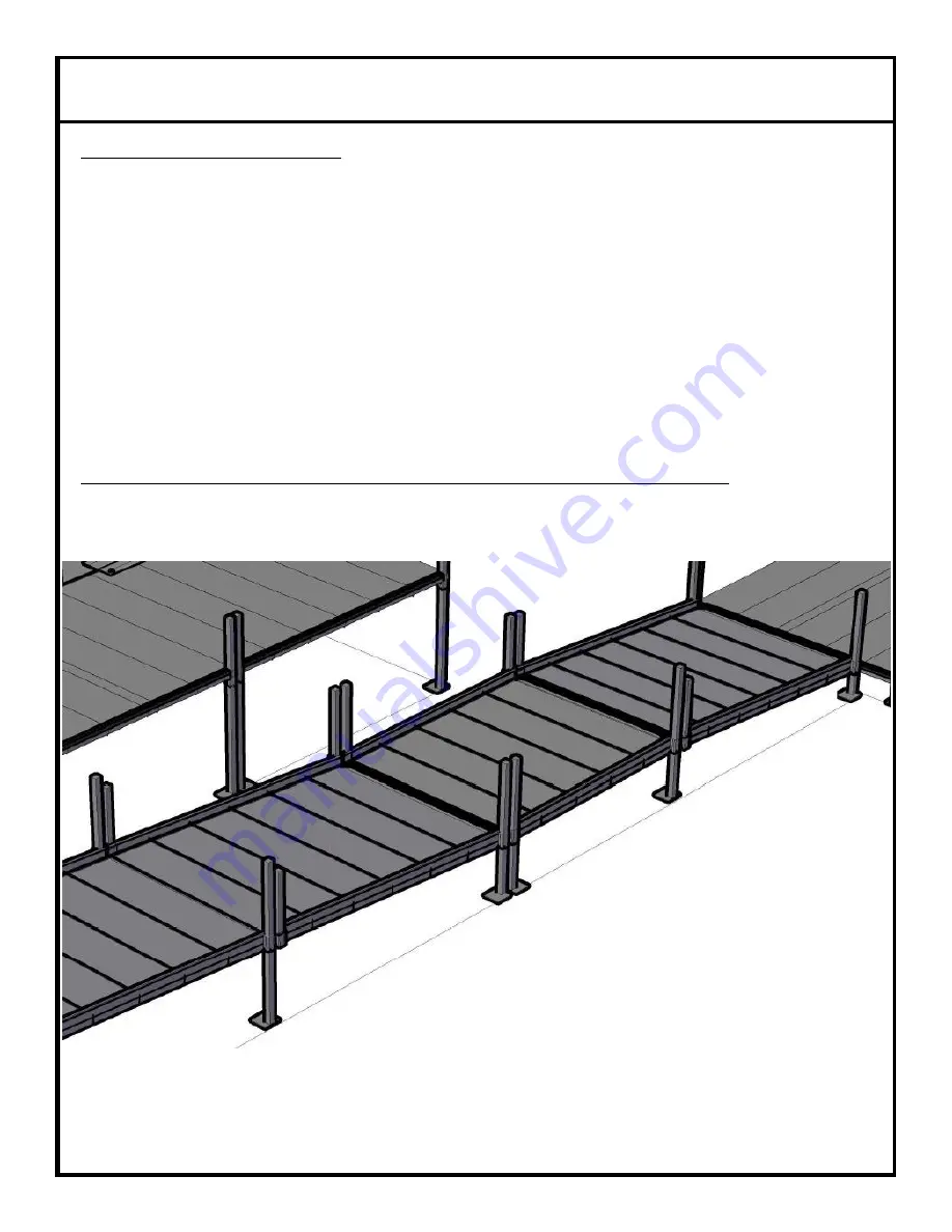
Ramp to Ramp/Ramp to Stop & Rest
1. Assemble ramps in the same manner as described above.
Use (4) legs if the section is a supporting section; use (2) legs
and (2) 14” inserts if the section is being supported by ”tongue and groove” design.
2. The lowest ramp section will always “tongue and groove” with the upper section of ramp.
3. Once the lower section is connected to the upper previous section, make necessary 1:12 slope adjustments, level
horizontally, and firmly secure .75” bolts.
4. When arriving at the last section of ramp in the system, no supports will be used. (4) 14” inserts will be used in place of
supports. The bottom of the section will fall directly on the ground.
5. The TT48 (48” transition tread—12” deep x 1” high) will slide from the side onto the “groove” part of the bottom of the
last section of ramp.
Center the TT48 with the last section
of ramp.
6.
Assemble the stop & rest (level landing after 30’ of run) like assembling a platform. The stop and rest will be treated like
a ramp section in relation to how a ramp section “tongue and grooves”. At the top and bottom.
All guard rails and hand rails will be installed after all platforms and ramps are assembled and set.
For questions about what each part is and the purpose it serves, please see the platform and ramp
description page as well as the hardware package description page.
For proper installation of guard rails, all ramp section have to be set at a 1:12 slope.


