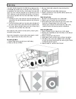
Servicing
7
The HRV 1500 SFD and HRV 1500 SFDE are designed to be
serviceable from either side. If access to the unit will only
be available from one side, the unit must be set up accord-
ingly. The unit is factory shipped to be serviced from the
front. (Blowers on the right when facing the unit. If servic-
ing is only accessible from the other side follow the proce-
dure below.
1. The Ebox must be removed from the front brackets and
mounted on the rear brackets provided on the other side
of the unit.
2. The filter divider panels must be removed and placed in
the unit so they can be removed from the opposite side.
3. The lower blower divider panel must be removed and
mounted in the unit from the other side.
Each panel on the unit can be removed by removing the
two bolts on the bottom.
Servicing is easiest by removing the side panels on both
sides to gain access to either side of the unit.
Servicing Filters
1. Remove filter service panel (one or both sides).
2. Remove first set of filters.
3. Remove filter divider panels (if only accessing from
one side).
4. Remove filters from behind filter divider panel.
5. Replace all filters. Ensure that filter divider panels are
reinserted into unit.
Servicing Cores
1. Remove core service panel (one or both sides).
2. Slide cores out (regular core maintenance).
3. When placing the cores back into the unit, ensure that
there are no gaps between any of the cores.
Ensure all H channels are flush with the ends of the
cores before the core service panel is re-attached.
Servicing Blowers
1. Remove blower service panel (one or both sides)
2. Unscrew the 2 bolts that connect the blower to the blower
rails of the unit.
3. Remove all wiring to the motors.
4. Slide blower back and lift to remove blower assembly.
5. If access to the unit is not available from both sides,
remove the blower divider panel by removing the 8 bolts
holding this panel in place.
6. Repeat steps 2-4 with the other blower.
Summary of Contents for 1500 SFDE
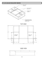
Page 10: ...10 Roof Curb Detail for Model HRV 1500 SFDE ...
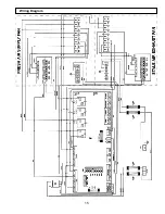
Page 15: ...15 Wiring Diagram ...


