Page -9-
R.E.S.C.U.E. Remote Control System
Manual C841.N2
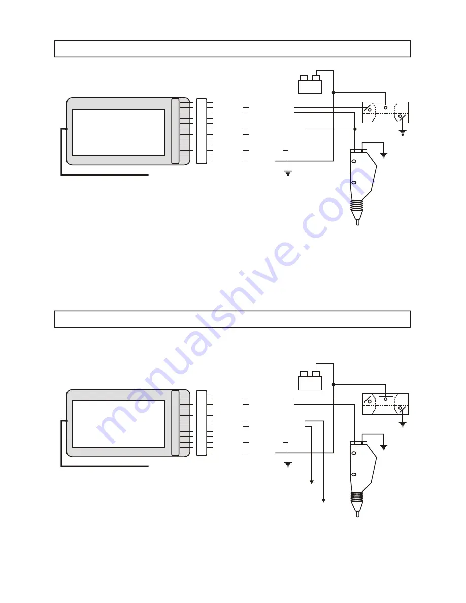
SETUP 2: Door Open and Door Lock / Door Unlock
12
11
10
09
08
07
06
05
04
03
02
01
PowerTouch Remote Control
System
Series 914 RF Receiver
This device complies with FCC rules part
15. Operation is subject to the following
1’ Co-axial Cable w/TNC Connector
12
11
10
09
08
07
06
05
04
03
02
01
Empty
Purple
Tan
Empty
Empty
Green/Red
Yellow/Red
Empty
Orange
Black
Empty
Red
Empty
Power +12v - 10 amp
Ch 3 - Output, 5 amp
Empty
Empty
Ch 1 - Output, +12v, 5 amp
Ch 2 - Output, +12v, 5 amp
Empty
Empty
Chassis Ground
Empty
Logic +12v
+12vFused @ 10 Amps
Ground
Ground
Black
Pull (+)
Red
Push (-)
*Red Lighted
Toggle Switch
*Door Unlatch Motor
*Note: Door Motor OPERATES ONLY
when Red Lighted Toggle Switch is ON.
SETUP 1: Door Open Only, Buttons 1 and 2 Open Door
To Door
Lock
Motor
To Door
Unlock
Motor
12
11
10
09
08
07
06
05
04
03
02
01
PowerTouch Remote Control
System
Series 914 RF Receiver
This device complies with FCC rules part
15. Operation is subject to the following
1’ Co-axial Cable w/TNC Connector
12
11
10
09
08
07
06
05
04
03
02
01
Empty
Purple
Tan
Empty
Empty
Green/Red
Yellow/Red
Empty
Orange
Black
Empty
Red
Empty
Power +12v - 10 amp
Ch 3 - Output, 5 amp
Empty
Empty
Ch 1 - Output, +12v, 5 amp
Not Used in this Application
Empty
Empty
Chassis Ground
Empty
Logic +12v
+12vFused @ 10 Amps
Ground
Ground
Black
Pull (+)
Red
Push (-)
*Red Lighted
Toggle Switch
*Door Unlatch Motor
*Note: Door Motor OPERATES ONLY
when Red Lighted Toggle Switch is ON.
(
-
)
Battery
(
+
)
(
-
)
Battery
(
+
)


