background image

 SET-UP

©

American Audio

®

   -   www.AmericanAudio.us   -   MCD-510™ Instruction Manual Page 6

 CUSTOMER SUPPORT

Customer Support:


 American Audio

®

 provides a toll free customer support line, to provide set up help and  

to answer any question should you encounter problems during your set up or initial operation. You may also visit 
us on the web at www.AmericanAudio.us for any comments or suggestions. For service related issue please 
contact American Audio

®

. Service Hours are Monday through Friday 9:00 a.m. to 5:00 p.m. Pacific Standard 

Time.
 

Voice:   

(800) 322-6337


Fax: 


(323) 582-2941


E-mail:  

support@americanaudio.us

Warning!


To prevent or reduce the risk of electrical shock or fire, do not expose this unit to rain or moisture. 

Caution!


There are no user serviceable parts inside this unit. Do not attempt any repairs yourself, doing so will 

void your manufactures warranty. In the unlikely event your unit may require service please contact customer 
support. Please do not return to your dealer without first contacting customer support. 

CAUTION:
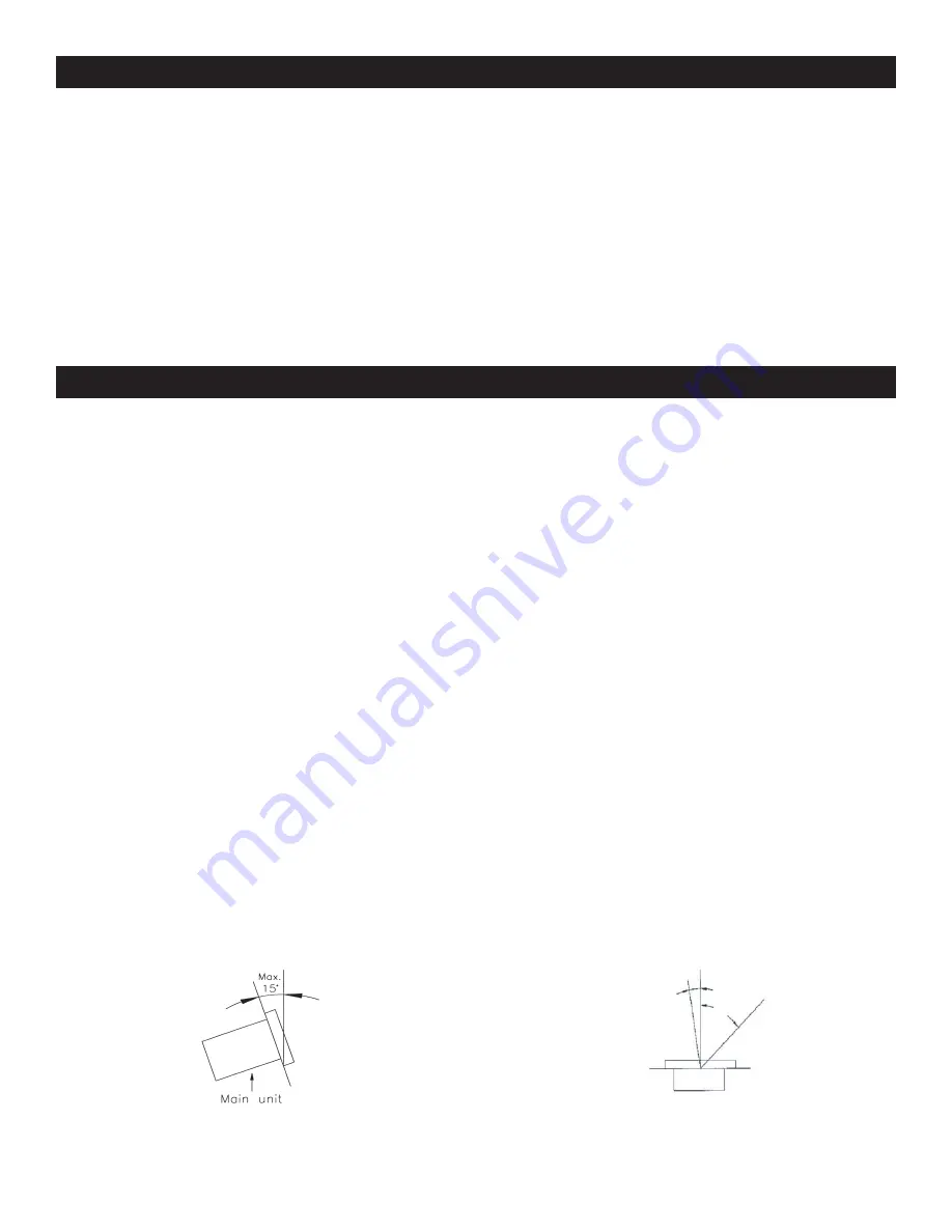
•  The player will work normally when the main unit is  
  mounted with the front panel within 15 degrees of  
  the vertical plane. If the unit is tilted excessively,  
  discs may not be loaded or unloaded properly.  
  (Figure 1)

CAUTION:
•  The LCD is designed to be clearly visible within the  
  angles shown in Figure 2. Mount the control unit  
  so that the visual angle is within this range.

Figure 2

Figure 1

1. Checking the Contents:      
  Be sure your MCD-510™ was shipped with the following:         
  1)  MCD-510™ Dual CD player unit. 


1)  MCD-510™ Controller Head Unit 

    2)  Dual Male to Male RCA cable. 


1)  Warranty card. 


  1)    Operating instructions (this booklet).
2. Installing the Units 
  1)   Place your unit on a flat surface or mount it in a secure rack mount case.
  2)   Be sure the player is mounted in a well ventilated area where it will not be exposed to direct sunlight,  
        high temperatures, or high humidity.
  3)   Try to place the unit as far as possible from TVs and tuners, as the unit may cause undesirable  
       

interference.

3. Connections
  1)   Be sure main power is connected last to prevent any electrical damage.
  2)  AUDIO CONNECTIONS: Use the included RCA cable to connect the MCD-510™ outputs to the
      

line inputs of a mixer. Never connect a CD player's output to a mixers "phono" inputs. 

  
CAUTION: Be sure to use the supplied control cables. Using a different type of cable may result in unit damage. 
To avoid server unit damage, be sure main power is off when connecting the control cables.

45°

Summary of Contents for MCD-510

Page 1: ...CD 510 Professional Dual Mp3 Compact Disc Player Operating Instructions 4295 Charter Street Los Angeles Ca 90058 www americanaudio us Rev 8 06 FLIPFLOP SINGLE TOTAL REMAIN TRACK M S F S GL C TN S GL C TN ...

Page 2: ...NDLING COMPACT DISC 20 WARRANTY 21 SPECIFICATIONS 22 CONTENTS Please Note All specifications and improvements to and in the design of this unit and this manual are subject to change at any time without any prior written or published noticed For service parts visit http parts americandj com FOR BEST CD R DISC PLAYBACK RESULTS IN THIS CD PLAYER PLEASE FOLLOW THESE GUIDELINES 1 High quality CD R Audio...

Page 3: ... PERSONNEL This equipment has been tested and found to comply with the limits for a Class B digital device pursuant to Part 15 of the FCC Rules These limits are designed to provide reason able protection against harmful interference in a residential installation This equipment generates uses and can radiate radio fre quency energy and if not installed and used in accordance with the instructions m...

Page 4: ... or pinched by items placed upon or against them paying particular attention to cords at plugs conveniencereceptacles andthepointwhere they exit from the product OUTDOOR ANTENNA GROUNDING If an outside antennaorcablesystemisconnectedtotheproduct be sure the antenna or cable system is grounded so astoprovidesomeprotectionagainstvoltagesurges andbuilt upstaticcharges Article810oftheNational Electric...

Page 5: ...e of some of these cleaner may damage the pick up lens be sure to follow extreme caution when using these types of cleaners American Audio www AmericanAudio us MCD 510 Instruction Manual Page 5 This unit has been thoroughly tested and has been shipped in perfect operating condition Carefully check the shipping carton for damage that may have occurred during shipping If the carton appears to be dam...

Page 6: ... the vertical plane If the unit is tilted excessively discs may not be loaded or unloaded properly Figure 1 CAUTION The LCD is designed to be clearly visible within the angles shown in Figure 2 Mount the control unit so that the visual angle is within this range Figure 2 Figure 1 1 Checking the Contents Be sure your MCD 510 was shipped with the following 1 MCD 510 Dual CD player unit 1 MCD 510 Con...

Page 7: ...e if your mixer s crossfader is all the way to the left player one is playing player two is in cue or pause mode If slice the fader at least 20 to the right player one will continue to play and player two will begin to play mixing both sides together When the crossfader is slid all the way to the right player two will is playing and player one will go into cue or pause mode You can create great ef...

Page 8: ...momentary pitch bend during playback Turning the wheel clockwise will increase the pitch percentage up to 16 and turning the wheel in the coun terclockwise direction will decrease the pitch percentage up to 16 The pitch bend will be determined on how fast you turn the wheel 2 LIQUID CRYSTAL DISPLAY LCD This high quality LCD Indicates all the functions play pause cue etc as they occur This display ...

Page 9: ... and return to cue mode In continuous mode the unit continues to play track by track and returns to cue mode after all tracks have played 7 PITCH PERCENTAGE SELECTOR Choose from pitch percentages of 4 8 and 16 See page 15 for more details 8 TIME The TIME button is used to changed the displayed time values Time can be displayed as elapsed track time remaining track time and total disc remaining tim...

Page 10: ...ctivate the LOOP mode To exit the loop press the LOOP OUT BUTTON 11 16 PLAY PAUSE BUTTON Each press of the PLAY PAUSE BUTTON causes the operation to change from play to pause or from pause to play 17 CUE Pressing the CUE button during playback immediately pauses playback and returns the track to the last set cue point The red CUE LED will glow when the unit is in cue mode The LED will also flash e...

Page 11: ...tch is used to control the unit s main power A blue LED directly above the power switch will glow to indicate main power is active 25 DRIVE 2 OPEN CLOSE Transport Tray Open Close This button is used to open and close the drive 2 transport tray NOTE When a disc is already loaded in the transport tray the tray will not open unless the unit is in pause or cue mode 26 DRIVE 2 TRANSPORT TRAY This tray ...

Page 12: ... sever damage to the unit Be sure the local power matches the unit s required power 31 VOLTAGE SELECTOR Because power supplies vary from location to location a voltage selec tor switch has been incorporated in the unit s design This switch can select a voltage input of 120v or 220v to accommodate the two major power source Always be sure to disconnect the power plug before changing the voltage Onl...

Page 13: ...the entire discs remaining time The time mode is changed by tapping on TIME BUTTON 8 The unit will indicate the ELAPSED time when neither the TOTAL REMAIN OR REMAIN indicators are showing Note When playing a Mp3 disc the TOTAL REMAIN time of a disc cannot be shown Only the REMAIN time and ELAPSED time of the track 38 REMAIN INDICATOR This indicator is in direct reference to the TIME METER 39 40 41...

Page 14: ...desired track by using either of the two TRACK BUTTONS 9 Tapping the TRACK BUTTONS 9 once will select either a higher or lower track You may hold down the TRACK BUTTONS 9 to change tracks con tinuously at a higher speed If you are using the TRACK BUTTONS 9 to select a new track during playback a track already playing the new track you selected will immediately begin playback as soon as the search ...

Page 15: ...nd The flashing bar will function regardless of which time mode the unit is in BASIC OPERATIONS CONT Activating the Pitch Slider 3 To activate the PITCH SLIDER 3 turn the pitch function on Press the PITCH BUTTON 12 to turn on the pitch func tion when the pitch function is activated a LED will begin to glow If the pitch function is not activated neither the PITCH SLIDER 3 nor the PITCH BEND BUTTONS...

Page 16: ...H BEND BUTTON 13 will provide a slow down The maximum range of the PITCH BEND BUTTONS is 16 The extent to which the speed changes is proportionate to the amount of time the button is pressed For example if the PITCH BEND BUTTON 13 is held down continuously the disc speed will increases and will continue to increase until reaches a maximum of 16 speed gain When you release the PITCH BEND BUTTON 13 ...

Page 17: ...s loop is a sound loop that plays continuously without sound interruption You can use this loop to create dramatic effect in your mixing This loop has no time limit and you could actually loop the entire length of disc You create a seamless loop between two continuous points of a disc 3 Press the OUT BUTTON 10 to set the end ing point for your Seamless Loop Figure 18 The OUT and IN BUTTON s will s...

Page 18: ... activated Press the SGL CTN BUTTON 6 to choose between SINGLE mode or CONTINUOUS mode 5 After they have both cued press the PLAY PAUSE BUTTON 16 on one of your drives to begin playback 6 If you have the cd player set to SINGLE mode the first cds single track will play and after it has ended the second cds track will immediately begin playback If the player is set to CONTIN UOUS mode the first cd ...

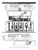
Page 19: ...MCD 510 Instruction Manual Page 19 FLIP FLOP SET UP INSTRUCTIONS SERIAL NO MODEL NO Q 2422 POWER SOURCE 115 230V 50 60Hz 13W MKII MADE IN CHINA MIN MAX TRIM OUTPUT A B BOOTH AUX IN FLIP FLOP RELAY CONNECTED DIRECT TO SPEAKERS FLIP FLOP RELAY CONNECTED TO A Q START MIXER S GL C TN S GL C TN ...

Page 20: ...ch as outdoors in winter Do not attempt to dry the disc with a hair dryer etc 2 PRECAUTION ON STORAGE After playing a disc always unload it from the unit Always store the compact disc in the jewel case protecting from dirt or damage Do not place discs in the following areas a Areas exposed to direct sunlight for a considerable time b Areas subject to accumulation of dust or high humidity c Areas a...

Page 21: ... not include maintenance cleaning or periodic check up During the period specified above American Audio will replace defec tive parts at its expense and will absorb all expenses for warranty service and repair labor by reason of defects in material or workmanship The sole responsibility of American Audio under this warranty shall be limited to the repair of the product or replacement thereof includ...

Page 22: ...to 140 F Accessories Dual RCA Cable for left and right channels Control 1 8 miniplug type 3 feet AUDIO SECTION Quantization 16 bit linear per channel Sampling rate 44 1 kHz at normal pitch Over sampling rate 8 times over sampling 1 bit D A converter D A conversion 16 bit Frequency response 0 4dB 20 Hz to 20 KHz Output level 2 0V 1dB Load impedance 47k ohm or more AUDIO CHARACTERISTICS TEST DISC TC...

Page 23: ...pick up Object lens drive system 2 dimensional parallel drive Tracking detection 3 spot beam detection Optical source Semiconductor laser Wave length 780nm SPECIFICATIONS American Audio www AmericanAudio us MCD 510 Instruction Manual Page 23 ...

Page 24: ... A Division of the American DJ Group of Companies American Audio World Headquarters 4295 Charter Street Los Angeles CA 90058 USA Tel 323 582 2650 Fax 323 582 2610 Web www americanaudio us E mail info americanaudio us ...

Reviews: