QSG-0135 r 1
Copyright 2017 by American Control Electronics® - All rights reserved. No part of this document may
be reproduced or retransmi�ed in any form without wri�en permission from American Control
Electronics®. The informa�on and technical data in this document are subject to change without
no�ce. American Control Electronics® makes no warranty of any kind with respect to this material,
including, but not limited to, the implied warran�es of its merchantability and fitness for a given
purpose. American Control Electronics® assumes no responsibility for any errors that may appear in
this document and makes no commitment to update or to keep current the informa�on in this
document.
+5V
AUX
COM
5 - 24V
Relay
Coil
OUT
IN
AUXILLARY OUTPUT
3-WIRE START/STOP*
COM INH
EN
CLOSE
TO
RUN
OPEN
TO
STOP
COM INH
EN
CLOSE TO RUN
OPEN TO COAST
CLOSE TO RUN
OPEN TO BRAKE
ENABLE / INHIBIT*
*Alternative wiring setups in Operation section
DIRECTION SWITCH
EN COM
DIR
Open for Forward
Close for Reverse
4 - 20 mA
SIG1 10V
COM
Common
(-)
Reference
(+)
VDC
mA
SIG1
ANALOG mA
0 - 10 VDC
-10 to 10 VDC
SIG1 10V
COM
Common
(-)
Reference
(+)
VDC
mA
SIG1
ANALOG VDC
10K Ohm
Speed / Torque
Adjust Potentiometer
SIG1 10V
COM
CW
VDC
mA
SIG1
POTENTIOMETER
US
10A
5A
2.5A
1.7A
A2
A1
F-
F+
L2
L1
COM SIG1 10V SIG2 DIR EN COM INH COM AUX
OUT
IN
SIG2
SIG1
VDC
mA
T1
T2
A180
A90
TACH
J504
STAT
LIMIT
1 2 3 4 5 6 7 8
ON
IR/T
RACC
FACC
MOP
RVCL
FWCL
MAX
OFS2
OFS1
TACH
0 ± 180 VDC
MOTOR
ARMATURE
0 ± 90 VDC
0 ± 180 VDC
MOTOR FIELD*
100 / 200 VDC
*DO NOT MAKE ANY
CONNECTIONS TO F- OR F+
IF USING A PERMANENT
MAGNET DC MOTOR
EARTH
GROUND
AC LINE INPUT
115 or 230 VAC
POWER
SWITCH
Tightening torque value of screw terminals on TB501 for logic connec�ons is 2.0 lb-in (0.23 N-m)
Tightening torque value of screw terminals on J501 for tach connec�ons T1 & T2 is 1.7 lb-in (0.19 N-m)
The logic connec�ons on TB501 are isolated up 3 kV.
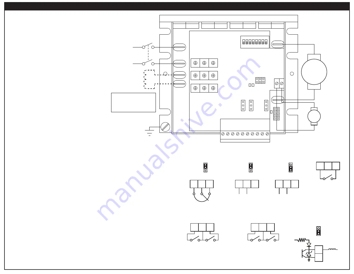
Line Input (115 or 230 VAC, 0 - 15 amps)
Connect the AC line power leads to terminals L1 and L2, or to a double-throw,
single-pole master power switch (recommended). The switch should be rated
at a minimum of 250 VAC and 200% of motor current.
Motor Armature (Up to 200 VDC, 0 - 11 Amps)
Connect the DC armature leads to terminals A1 and A2. If the motor does not
spin in the desired direc�on, power down the drive and reverse these connec�ons.
Field (Up to 200 VDC, 0.74 Amps)
At 115 VAC, connect the field leads to terminals F+ and L1 for a 50 VDC field or
to F+ and F- for a 100 VDC field. At 230 VAC, connect the field leads to terminals
F+ and L1 for a 100 VDC field or to F+ and F- for a 200 VDC field.
Do not make any connec�ons to F+ and F- if using a permanent magnet motor.
Tach Feedback (Input up to 180 VDC)
If using a tachogenerator, connect to terminals T- (nega�ve) and T+ (posi�ve).
See jumper se�ngs in the Startup sec�on.
Do not make
any connec�ons to T- or T+ unless using a tachogenerator.
Remote Adjust Poten�ometer
Use a 10K ohm, 1/4 W poten�ometer for control. Connect the counter-clockwise
end of the poten�ometer to COM, wiper to SIG1, and the clockwise end to 10V.
If the poten�ometer works inveresly of desired func�onality, (i.e. to increase motor
speed, you must turn the poten�ometer counterclockwire), power off the drive and
swap the COM and +V connec�ons.
Analog Signal
To use an analog signal instead of a poten�ometer, connect the signal nega�ve (-)
to COM and the signal reference (+) to SIG. Set jumper SIG1 to VDC if using a
poten�ometer or analog voltage signal, or to mA if using a 4-20 mA analog signal.
Direc�on
Short terminals COM and DIR to change the direc�on of the motor.
If no direc�on switch is desired, leave this connec�on open.
Enable
The enable is used to start the drive. It can be set for a normally open or normally
closed configura�on. Disabling the drive will cause the motor to coast to a stop.
The enable can also be used as a Start switch in a 3-Wire Start/Stop setup.
Do not use the enable for emergency stopping.
Inhibit
Ac�via�ng the inhibit will regenera�vely brake the motor to a stop. It bypasses the
FACC and RACC trim pots. It can be set for a normally open or normally closed
configura�on. The inhibit can also be used as a Stop switch in a 3-Wire Start/Stop setup.
Do not use the inhibit for emergency stopping.
Connections


