background image

21

To Convert from Natural Gas to Liquid Propane (L.P.) Gas

NOTE: ALL

 dryers are sold as natural gas, unless otherwise specified at the time the dryer order was

placed.  For L.P. gas the dryer 

must be

 converted as follows.

1. Refer to “Replace Gas Valve” and follow steps 1 through 6.

2. Remove the four (4) screws which secure the top cap assembly.  This assembly contains the regulator

adjustment screw and the terminal connections.

3. Replace the top cap assembly with the L.P. version.

4. Unscrew main burner orifices and replace with L.P. orifices.

NOTE:

Use extreme care when removing and replacing orifices.  These orifices are made of brass and
are easily damaged.

5. Reverse the procedure for reinstalling valve assembly to the dryer.

WARNING:

Test 

ALL

 connections for leaks by brushing on a soapy water solution.  NEVER TEST

FOR LEAKS WITH A FLAME.

NOTE:

There is no regulator provided in an L.P. dryer.  The L.P. gas pressure 

must be

 regulated at

the source (L.P. tank) or an external regulator 

must be

 added to each dryer.

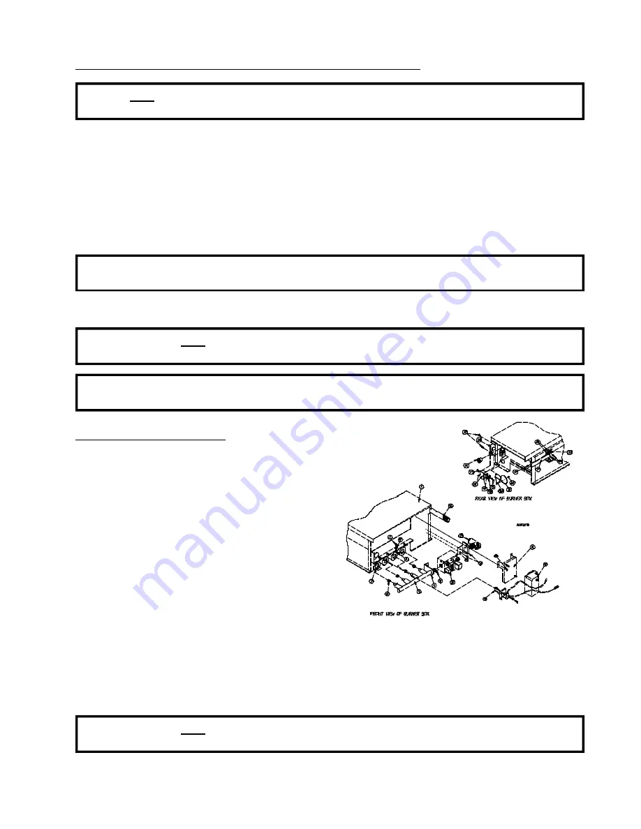
To Replace Burner Tubes

1. Refer to “Replace Gas Valve” and follow steps

1 through 6.

2. Remove four (4) screws securing manifold rest

and remove rest.

3. Remove the screws securing the front flanges

of the burner tubes to the burner tube rest.

4. Remove the screws securing the burner tube

rest to the oven and remove this rest.

5. Remove screws securing the sight hole disk and burner box cover plate to the oven and remove both of

these pieces.

6. Remove burner tubes by sliding them out.

7. Replace by reversing procedure.

WARNING:

Test 

ALL

 connections for leaks by brushing on a soapy water solution.  NEVER TEST

FOR LEAKS WITH A FLAME.

Summary of Contents for AD-758

Page 1: ...8 Service Manual 052802ASILVA mcronan ADC Part No 450418 American Dryer Corporation 88 Currant Road Fall River MA 02720 4781 Telephone 508 678 9000 Fax 508 678 9447 e mail techsupport amdry com www amdry com ...

Page 2: ..._____________________ ________________________________________________________________________________________ ________________________________________________________________________________________ Replacement parts can be obtained from your reseller or theADCfactory When ordering replacement parts from the factory you can FAX your order to ADC at 508 678 9447 or telephone your order directly to...

Page 3: ...INE OR OTHER FLAMMABLE VAPORS AND LIQUIDS IN THE VICINITY OF THIS OR ANY OTHER APPLIANCE FOR YOUR SAFETY DO NOT DRY MOP HEADS IN THE DRYER DO NOT USE DRYER IN THE PRESENCE OF DRY CLEANING FUMES CHILDREN SHOULD NOT BE ALLOWED TO PLAY ON OR NEAR THE DRYERS WARNING CHILDREN SHOULD BE SUPERVISED IF NEAR DRYER S IN OPERATION DRYERS SHOULD NEVER BE LEFT UNATTENDED WHILE IN OPERATION CAUTION WARNING The ...

Page 4: ...d specified in the installation manual included with the dryer WARNING DRYER MUST NEVER BE OPERATED WITHOUT THE LINT FILTER OR SCREEN IN PLACE EVEN IF AN EXTERNAL LINT COLLECTION SYSTEM IS USED The wiring diagram for the dryer is located in the front electrical control box area ...

Page 5: ...on Microprocessor 10 C Control Box 10 D Direct Spark Ignition DSI Module Gas Models Only 11 E Gas Burner Assembly 11 F Drive Motor 11 G Blower Motor and Impellor Non Reversing 12 H Blower Motor and Impellor Reversing 12 I Idler Assembly 12 J Basket Tumbler Bearing and Pulley Arrangement 12 K Basket Tumbler 13 L Main Door Switch 13 M Sail Switch Gas Models Only 13 N Hi Limit Gas Models Only 14 O Au...

Page 6: ...ion F Pulleys 31 I V Belts Refer To The Illustrations In Section F Pulleys 33 J Motors and Impellors 34 K To Replace Lint Drawer Switch 36 SECTION VI TROUBLESHOOTING 37 SECTION VII ELECTRICAL TROUBLESHOOTING 41 A Phase 5 OPL System Diagnostics 41 B L E D Display Indicators 42 C L E D Display Codes 44 D Computer Logic and Wiring Diagram 48 SECTION VIII TECHNICAL INFORMATION 53 A Motor Data Label Hi...

Page 7: ...O NOT try to light any appliance b DO NOT touch any electrical switch c DO NOT use any phone in your building d Clear the room building or area of ALL occupants e Immediately call your gas supplier from a neighbor s phone Follow the gas supplier s instructions f If you cannot reach your gas supplier call the fire department 4 Installation and service must be performed by a qualified installer serv...

Page 8: ...ill VOID THE WARRANTY 9 UNDER NO CIRCUMSTANCES should the dryer door switches lint door switch heat safety circuit ever be disabled WARNING PERSONAL INJURYOR FIRE COULD RESULT 10 This dryer is not to be used in the presence of dry cleaning solvents or fumes 11 Remove articles from the dryer as soon as the drying cycle has been completed WARNING Articles left in the dryer after the drying and cooli...

Page 9: ...ROM COMBUSTIBLE MATERIALS GASOLINE AND OTHER FLAMMABLE VAPORS AND LIQUIDS NOTE Suggested time intervals shown are for average usage which is considered six 6 to eight 8 operational running hours per day Clean lint drawer and screen every third or fourth load NOTE Frequency can best be determined at each location DAILY Beginning of each work shift Clean lint from the drawer and screen Inspect lint ...

Page 10: ...avoid using harsh abrasives A product intended for the cleaning of appliances is recommended B ADJUSTMENTS 7 DAYS AFTER INSTALLATION AND EVERY 6 MONTHS THEREAFTER Inspect bolts nuts screws bearing setscrews grounding connections and nonpermanent gas connections unions shutoff valves and orifices Motor and drive belts should be examined Cracked or seriously frayed belts should be replaced Tighten l...

Page 11: ...e appropriate Installation Manual for recommended distances and minimum allowances required When the dryer is operating it draws in room air heats it passes this air through the basket tumbler and exhausts it out of the building Therefore the room airmust be continually replenished from the outdoors If the make up air is inadequate drying time and drying efficiency will be adversely affected Ignit...

Page 12: ...al codes and ordinances and must be done by a qualified professional NOTE Undersized gas piping will result in ignition problems and slow drying and can create a safety hazard The dryer must be connected to the type of gas natural or L P indicated on the dryer data label If this information does not agree with the type of gas available contact the reseller who sold the dryer or contact the factory...

Page 13: ...e is correct and consistent NOTE Water column pressure requirements measured at the pressure tap on the gas valve body Natural Gas 3 5 Inches 8 7 mb Water Column Liquid Propane L P Gas 10 5 Inches 26 1 mb Water Column 6 If computer program changes are required refer to the Phase 5 OPL Operator s Manual ADC P N 112147 for details 7 The dryer should be operated through one 1 complete cycle to assure...

Page 14: ...NON MICROPROCESSOR On models without microprocessors a timer is used to set a specific time Most non microprocessor dryers are built with dual timers a 60 minute dry timer and a 15 minute cool down timer The temperature selector switch selects the Hi Perm Press or Lo Temp The Push To Start relay activates the dryer which starts the drying cycle PRIOR TO NOVEMBER 3 2000 AS OF NOVEMBER 3 2000 C CONT...

Page 15: ...th a gas burner assembly consisting of four 4 burner tubes gas valve spark ignition probe assembly sail switch and hi limit thermostat The inlet piping enters through the rear of the dryer on the left hand side viewing from the front and runs to the front of the dryer where the gas valve is located F DRIVE MOTOR The totally enclosed fan cooled T E F C drive motor is located approximately lower cen...

Page 16: ... approximately on the lower center of the dryer The idler assembly consists of two 2 idler pulleys the small and large pulleys The idler s main purpose is to reduce the speed and increase torque provided to the basket tumbler bearing Also at the idler assembly belt tension can be adjusted J BASKET TUMBLER BEARING AND PULLEYARRANGEMENT The basket tumbler bearing and pulley arrangement is located vi...

Page 17: ...n door switch is a safety device and should never be disabled M SAILSWITCH GAS MODELS ONLY The sail switch is located on the front of the burner box A sail switch consists of a round damper plate on a lever arm which is in contact with an electric switch When the air blower comes on it draws air through the gas burner This creates a negative pressure inside the burner box and this negative pressur...

Page 18: ...t senses the heated air after it has passed through the basket tumbler If the air temperature gets too hot the thermostat will shut off the burner The dryer willnot run until the air temperature cools down At this time the thermostat will reset Basket tumbler and blower will run but dryer will not heat P LINT DRAWER The lint drawer is a pullout type and is located at the bottom of the dryer in the...

Page 19: ...or cool down Air supply is 80 PSI 10 PSI 5 51 bars 0 68 bars S COMPRESSED AIR REQUIREMENTS The dryer requires an external supply of air 2 5 cfm 80 PSI 0 07 cmm 0 68 bars on the steam models the air is necessary to operate the damper system On both steam as well as the gas model the air is necessary required for the blower air jet operation to clean lint from the impellor fan squirrel cage type T T...

Page 20: ... for use by an untrained person making repairs Service work should be performed by competent technicians in accordance with local state and federal codes When contacting the factory for assistance always have the dryer model and serial numbers available CAUTION Observe ALL safety precautions displayed on the dryer or specified in this manual before and while making repairs Before considering repla...

Page 21: ... A and B factors are printed on a label located on the rear of the control panel refer to the illustration above 8 Reestablish electrical power to the dryer To Replace Keyboard Touch Pad Label Assembly 1 Discontinue electrical power to the dryer 2 Unplug keyboard touch pad ribbon from rear of computer 3 Slowly peel off and remove keyboard touch pad label assembly from control panel 4 Peel paper ba...

Page 22: ...crewdriver to slowly pry the fastener off 5 Disconnect the two 2 orange wires from the high heat 225º F 107º C thermostat and remove modular bracket connector wires and probe from bracket assembly 6 Install new sensor probe assembly ADC P N 880251 by reversing procedure 7 Reestablish electrical power to the dryer NOTE If when power is reestablished the computer display reads dSFL check for a loose...

Page 23: ...on on page 18 1 Discontinue electrical power to the dryer 2 Close shutoff valve s in gas supply line 3 Disconnect gas valve wiring NOTE Identify location of each wire for correct reinstallation 4 Break union connection before gas valve 5 Loosen and remove screws 4 securing pipe brackets to burner 6 Remove gas valve manifold assembly from dryer 7 Remove valve mounting bracket manifold and piping fr...

Page 24: ...ube rises showing the exact water column pressure NOTE Manometers are available from the factory by ordering ADC P N 122804 1 To test gas water column pressure a Connect water column test gauge connection to gas valve pressure tap 1 8 N P T This pressure tap is located on the outlet manifold side of the valve b Start dryer With burner on the correct water column reading in inches would be Natural ...

Page 25: ...he dryer WARNING Test ALL connections for leaks by brushing on a soapy water solution NEVER TEST FOR LEAKS WITH A FLAME NOTE There is no regulator provided in an L P dryer The L P gas pressure must be regulated at the source L P tank or an external regulator must be added to each dryer To Replace Burner Tubes 1 Refer to Replace Gas Valve and follow steps 1 through 6 2 Remove four 4 screws securing...

Page 26: ...t Thermostat Gas Models Only This thermostat is an important safety device serving as an added protection against failure of the airflow sail switch to open in the event of motor failure or reduced airflow condition IMPORTANT Under no circumstances should heat circuit safety devices ever be disabled 1 Discontinue electrical power to the dryer 2 Disconnect wires from hi limit thermostat 3 Remove sc...

Page 27: ...TE DO NOT remove the screws 4 Remove bracket assembly by slightly sliding bracket towards the rear of the dryer and to the left 5 Disconnect sensor bracket harness connector and remove bracket assembly from dryer 6 Disconnect the two 2 orange wires from the thermostat 7 Disassemble thermostat from bracket assembly by removing the two 2 mounting screws washers and nuts 8 Reverse this procedure for ...

Page 28: ...from switch 5 Disassemble door switch from bracket by removing two 2 Phillips screws and nuts securing on switch to the housing 6 Reverse this procedure for installing new door switch 7 Reestablish electrical power to the dryer IMPORTANT UNDER NO CIRCUMSTANCES should the door switch be disabled To Replace Main Door Assembly 1 Remove screws holding top hinge block to front panel 2 Remove door by li...

Page 29: ...the silicone contact between glass and door 8 The door assembly should now be put in an area where it will not be disturbed for at least 24 hours Depending on the conditions the curing time of this adhesive is 24 to 36 hours 9 After 24 hour curing period install main door on dryer by reversing Step 1 To Replace Front Panel 1 Discontinue electrical power to the dryer 2 Remove main door switch and b...

Page 30: ... installing new sail switch Adjust sail switch as described in the next section To Adjust Sail Switch With the dryer operating at a high temperature setting pull the sail switch away from the burner The sail switch should open and extinguish the burner Let the sail switch damper return to the burner wall The sail switch should close to restart the burner ignition cycle If the sail switch circuitdo...

Page 31: ...heave to be drawn in contact with the flange of the bushing This gap should measure from 1 8 to 1 4 Proper cap screw torque is 30 ft lbs 133 4 newtons If greater tightening forces are applied excess pressures will be created in the hub of the mounted sheave which may cause it to crack To Replace Small Idler Pulley 1 Loosen V belts Rotate pulley and roll V belts out of grooves 2 Remove cap screws f...

Page 32: ... loosely inserted bushing remains fully expanded to provide a sliding fit on the shaft 6 Insert key on the shaft then slide sheave to desired position with cap screw heads to the outside 7 Tighten cap screws progressively There should remain a gap between the sheave hub and the flange of the bushing IMPORTANT Tighten screws evenly and progressively Never allow the sheave to be drawn in contact wit...

Page 33: ...mbler Alignment Vertical Up and Down Adjustment 1 Discontinue electrical power to the dryer 2 Remove back guard 3 Loosen the two 2 vertical holding bolts on the side at the top of the bearing box one 1 on each side 4 Back off jam nuts on vertical adjustment bolts 5 Turn these bolts clockwise CW evenly to raise basket tumbler or counterclockwise CCW evenly to lower basket tumbler 6 Rotate basket tu...

Page 34: ... Basket Tumbler or Basket Tumbler Support 1 Discontinue electrical power to the dryer 2 Follow procedure for removal of main door assembly 3 Follow procedure for removal of front panel assembly 4 Remove back guard 5 Remove basket tumbler belts 6 Remove basket tumbler pulley 7 Remove basket tumbler assembly and support a Loosen the two 2 setscrews on both the pillow block bearing collars b Remove t...

Page 35: ...asket tumbler vertical lateral alignment and adjust if necessary 11 Replace back guard 12 Reestablish electrical power to the dryer H BEARINGS REFER TO THE ILLUSTRATIONS IN SECTION F PULLEYS To Replace Rear Basket Tumbler Support Pillow Block Bearing 1 Discontinue electrical power to the dryer 2 Remove back guard 3 Remove basket tumbler pulley 4 Loosen lateral adjustment jam nuts and bolts Refer t...

Page 36: ...r 8 Replace by reversing steps 2 through 6 NOTE Before replacing back guard check basket tumbler lateral vertical adjustment as well as belt adjustment and readjust if necessary 9 Reestablish electrical power to the dryer To Replace Front Idler Shaft Pillow Block Bearing Bearing nearest the back of the dryer 1 Discontinue electrical power to the dryer 2 Remove V belts from idler pulleys 3 Remove b...

Page 37: ...ult If the pulleys are not properly aligned excessive belt wear will result Proper belt tension will allow 1 2 displacement under normal thumb pressure at mid span of belt NOTE Belts must always be replaced in pairs matched sets V Belt Tension Adjustment Basket Tumbler to Idler 1 Discontinue electrical power to the dryer 2 Back off jam nuts on idler adjustment belts 3 Tighten belts by turning both...

Page 38: ...mount bolts and jam nuts 8 Reestablish electrical power to the dryer To Replace V Belts 1 Loosen tension on V belts so that they can easily be rolled off pulleys 2 Replace V belts 3 Retighten V belts and adjust tension and alignment per previous instructions NOTE Always replace V belts in pairs J MOTORS AND IMPELLORS To Replace Drive Motor 1 Discontinue electrical power to the dryer 2 Remove drive...

Page 39: ...ount at no less than 3 16 clearance 7 Install impellor onto new motor shaft 8 Reinstall the motor mount and reconnect the motor harness 9 Reestablish electrical power to the dryer To Replace Impellor Direct Drive To replace the impellor follow steps 1 through 4 of To Replace Impellor Motor Direct Drive To Replace Reversing Impellor Motor Fan Shaft Drive 1 Discontinue electrical power to the dryer ...

Page 40: ...nded jam nuts and the side panel 6 Reestablish electrical power to the dryer K TO REPLACE LINT DRAWER SWITCH 1 Discontinue electrical power to the dryer 2 Remove lint drawer and lint door 3 Disconnect both 4 pin connectors at the rear of the lint switch cover 4 Remove the four 4 screws holding the lint switch cover on 5 Remove lint switch cover and disconnect the two 2 terminals of the switch 6 Re...

Page 41: ... service the equipment OBSERVE ALL SAFETY PRECAUTIONS DISPLAYED ON THE EQUIPMENT OR SPECIFIED IN THIS MANUAL WHILE MAKING REPAIRS Refer to Electrical Troubleshooting section for a detailed troubleshooting procedure for electrical components A No display on computer 1 Open circuit breaker switch or blown fuse 2 Tripped overload on the blower MTR 3 Bad wiring connection 4 Faulty microprocessor contr...

Page 42: ...obe assembly or probe is misadjusted 5 Failed ignition Direct Spark Ignition DSI module 6 Failed gas valve 7 Failed microprocessor controller computer F Dryer operates probe sparks but gas does not flow 1 Dryer gas shutoff valve is closed 2 Failed gas valve open coil in valve 3 Loose wiring connection from DSI module to gas valve Check voltage at gas valve 4 Failed DSI module G Dryer operates prob...

Page 43: ...nally low or high voltage supply 2 Motor bearing failure 3 Bearing failure in drive system 4 Motor vents are blocked with lint 5 Failed motor 6 Insufficient make up air J Overload for impellor fan motor is tripping 1 Either an exceptionally low or high voltage supply 2 Motor bearing failure 3 Motor vents are blocked with lint 4 Failed motor 5 Failed overload 6 Out of balance impellor fan 7 Insuffi...

Page 44: ...connector b Connection at computer harness connector 4 Faulty microprocessor controller computer M Dryer does not start Display reads door 1 Main door is open 2 Lint drawer is open 3 Faulty main door or lint door switch 4 Open circuit in either main door or lint drawer switch harnesses 5 Faulty 24V transformer N There is excessive vibration coming from the basket tumbler 1 Basket tumbler is out of...

Page 45: ...ode L E D display of certain failure codes along with indicators both in the L E D display and the outputs of each relay and door switch circuit to easily identify failures Diagnostic L E D Display Failure Codes 1 door Indicates door switch circuit is open a Keyboard touch pad entry was made while main door or lint drawer is open or b There is a fault in the door switch circuit external of the Pha...

Page 46: ...one bUZ will sound for approximately 5 seconds and the light emitting diode L E D display will read Hot until the temperature has dropped to 220º F 104º C or lower and the Phase 5 OPL microprocessor controller computer is manually reset by pressing the Clear Stop key B L E D DISPLAY INDICATORS The L E D indicator dots located at the top portion of the L E D display as shown in the illustration bel...

Page 47: ...e was elsewhere i e the dryer s door switch circuit the L E D display would read door if a keyboard touch pad entry was attempted If the display indicator dots are on and the DOOR L E D input and the motor heat output L E D s are on yet the motor and or heat is not active on then the problem is elsewhere in the dryer 2 HEAT Output L E D Indicator a If the dryer is started and there is NO HEAT yet ...

Page 48: ...er motor is not operating and the REV indicator is on then the problem fault is elsewhere i e external of the Phase 5 OPL microprocessor controller computer C L E D DISPLAY CODES The L E D display informs the user of cycle status and program verification and displays important diagnostic and fault codes 1 Display Operating Status a Cycle in Progress While the dryer is operating the display will re...

Page 49: ...in the reverse counterclockwise CCW direction Illus No 6 FORWARD INDICATOR This indicator dot is functional only for models with the reversing action option This indicator willbe on when the basket tumbler is in the forward clockwise CW direction In addition when the anti wrinkle program is active this indicator dot will be on whenever the microprocessor controller computer is in the guard program...

Page 50: ...cle B CY C Preprogrammed Cycle C CY d Preprogrammed Cycle D CY E Preprogrammed Cycle E CY F Preprogrammed Cycle F CYCL tinE Cycle Display Time d Dryness Level percentage of extraction Numerical Value donE Drying or Cooling Cycles Complete or Dryer is in Anti Wrinkle Program door Door Circuit is Open or Fault in Door Switch Circuit dr Drying Cycle in Progress drY LEuL Dryness Level percentage of ex...

Page 51: ...ition MAnU Manual Mode MGrd Maximum Guard Time nbUZ No Buzzer tone nFLS No Flash Display nGrd Anti Wrinkle Program Is Not Active nrEu No Reverse ProG Program Mode rEu Reverse SC Special Cool Down SEFL Rotational Sensor Circuit Failure SEn Rotational Sensor Selected SPIn tInE Spin Time Sr Select Reverse Stop tInE Stop Time tEnP tInE Temperature Display Time tinE Time ...

Page 52: ...s the contactors and Direct Spark Ignition DSI module which controls dryer functions NOTE When contacting ADC with electrical questions please have on hand the correct wiring diagram number for your particular dryer This number is located on the top right hand corner of the diagram It is a six 6 digit number followed by a letter to distinguish the revision dates refer to the illustration below The...

Page 53: ... light on NOTE In this next section when checking for voltage you are looking for 24 VAC unless otherwise specified B Drive motor reverses but does not go forward blower motor runs 1 If computer dot first dot on the left does not come on replace the computer 2 Check for voltage across the coil markings A1 and A2 of the forward contactor located in the rear panel box The contactor according to your...

Page 54: ...nals the problem is bad wire s or termination s between the arc suppressor A S board and the computer 15 pin connector no 8 or a faulty computer D Blower motor does not operate drive motor runs 1 Check for voltage across terminals A1 and A2 of the impellor contactor This is the single contactor in the rear control box If voltage is present check for voltage across the blower motor If there is volt...

Page 55: ...of the two 2 components replace that component 4 If voltage is present refer to DSI Technical Manual P N 450119 or if equipped with ADC style DSI module refer to Technical Manual P N 450142 F No Heat drive and blower motors run display reads normal Steam Models 1 Check for voltage across terminal block nos 3 and 7 If no voltage is present problem is bad wire s or termination s between terminal blo...

Page 56: ...race the voltage through the lint drawer switch and the main door switch and their connectors J3 and J4 to the 15 pin modular connector 2 If voltage stops at any one 1 of the switches replace the switch If voltage stops at a connector check the termination or wire back to the prior connector H Microprocessor reads DSFL NOTE Before continuing with this section check the 0 125 mA fuse on the compute...

Page 57: ...h voltage rating Removing the cap reveals the wiring to the motor On each wire there is a tag with a number which corresponds to the number on the motor data label Depending on whether the dryer is operating on low voltage or high voltage the wiring should match the motor data label as follows The dots and lines represent connections refer to the illustration above For example On Low Voltage wire ...

Page 58: ...umber allows ADC to gather information on your particular dryer 3 MANUFACTURING CODE NUMBER The manufacturing code number is a number issued by ADC which describes ALL possible options on your particular model 4 TYPE OF HEAT This describes the type of heat for your particular dryer gas either natural gas or liquid propane L P gas or steam 5 HEAT INPUT for GAS DRYERS This describes the heat input i...

Page 59: ...in a position so that readings can be taken at eye level 4 Fill manometer with water as shown in the illustration to the zero level 5 Start dryer With burner on take a reading a Read water level at the inner tube Readings should be taken at eye level b Correct readings should be Natural Gas 3 5 inches 8 7 mb water column W C Liquid Propane L P Gas 10 5 inches 26 1 mb water column 6 If water column...

Page 60: ...ench 3 8 Socket Wrench 1 2 Socket or Open End Wrench 1 4 Open End Wrench 5 16 Socket or Open End Wrench 1 2 Socket Wrench 7 16 Socket or Open End Wrench 5 16 Nut Driver 12 Pipe Wrench 2 1 8 T Shaped or L Shaped Allen Wrench 3 16 T Shaped or L Shaped Allen Wrench Wire Cutters 1 2 Allen Wrench 3 8 Allen Wrench Channel Locks Manometer ADC P N 122804 MP Pin Extraction Tool ADC P N 122800 ...

Page 61: ...ADC 450418 1 06 16 02 20 ...

Reviews: