background image

18

American Dryer Corp.

113335 - 12

NOTE: The dryer must be isolated from the gas supply
piping system by closing its individual manual shutoff valve
during any pressure testing of the gas supply piping
system at test pressures equal to or less than 1/2 psig (3.5
kPa).

Steam Information ____________________

It is your responsibility to have all steam plumbing connections
made by a qualified professional to ensure that the installation
is adequate and conforms to local and state regulations or
codes.

IMPORTANT: Failure to comply with the requirements
stipulated in this manual can result in component failure,
which will void the warranty.

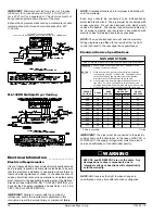
NOTE: The dryer is manufactured with a pneumatic
(piston) damper system, which requires an external supply
of clean, dry, and regulated air of 0.75 cfh (0.02 cmh) @ 80
psi +/- 10 psi (5.51 bar +/- 0.68 bar).  Refer to Steam
Damper Air System Connections on the following page.

Steam Coil pH Level

The normal pH level for copper type steam coils must be
maintained between a value of 8.5 to 9.5.  For steel type
steam coils the pH level must be maintained between a value
of 9.5 to 10.5.  These limits are set to limit the acid attack of
the steam coils.

IMPORTANT: Coil failure due to improper pH level will void
the warranty.

Steam Requirements, High Pressure

Inlet .................... 1-1/4” supply line connection

qty. 1 at top manifold.

Return ................ 1-1/4” return line connection

qty. 1 at bottom manifold.

Operating Steam Pressure

 Maximum

125 psig

*

862.84 kPa

 Heat Input (Normal Load)

13


Bhp

 Consumption (Approximate)

450 lb/hr

202.2 kg/hr

Shaded areas are stated in metric equivalents

*  The minimum operating pressure for optimum results is 100 psig (689.47
kPa).

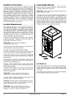
Installation Instructions

To ensure that an adequate supply of steam is provided, be
sure that the steam supply lines and steam return lines are
sized and laid out as stipulated in this manual.  Inadequate
steam supply and steam return lines or improper steam
plumbing will result in poor performance and can cause
component failure.  Clean, dry, and regulated steam must be
provided to the dryer.

IMPORTANT: Steam coil failure due to water hammer by
wet steam will void the warranty.

The pressure of the condensate in the steam supply line will
cause water hammer and subsequent heat exchanger (steam
coil) failure.  The steam supply connection into the main
supply line must be made within a minimum 12-inch (30.48
cm) riser.  This will prevent any condensate from draining
towards the dryer.

The steam supply line to the dryer must include a 12-inch
(30.48 cm) riser along with a drip trap and check valve.  This
will prevent any condensate from entering the steam coil.

Flexible hoses or couplings must be used.  The dryer vibrates
slightly when it runs and this will cause the steam coil
connections to crack if they are hard piped to the supply and
return mains.

Shutoff valves for each dryer should be installed in the supply,
return, and drip trap return lines.  This will allow the dryer to
be isolated from the supply and return mains if the dryer needs
maintenance work.

Install an inverted bucket steam trap and check valve for
each unit at least 12-inch (30.48 cm) below steam coil as
close to the coil as possible.

A trap with a capacity of 1,200 lb (544 kg) of condensate per
hour at 125 psi (8.61 bar) is needed for each unit.

A 3/4-inch (19.05 mm) vacuum breaker should be installed
for each unit in the piping.  This will prevent the condensing
steam from causing a vacuum inside the coil and possibly
damaging the coil.

Dryers with optional solenoid valve must be mounted with
coil positioned directly above the valve body.

The supply and return lines should be insulated.  This will
save energy and provide safety for the operator and
maintenance personnel.

Water pockets in the supply line, caused by low points, will
provide wet steam to the coil possibly causing coil damage.
All horizontal runs of steam supply piping should be pitched
1/4-inch (6.35 mm) for every 1 foot (0.31 meters) back towards
the steam supply header causing any condensate in the line
to drain to the header.  Install a bypass trap in any low point
to eliminate wet steam.

Summary of Contents for ML-130 III

Page 1: ...s de bien suivre les instructions données dans cette notice pour réduire au minimum le risque d incendie ou d explosion ou pour éviter tout dommage matériel toute blessure ou la mort Ne pas entreposer ni utiliser d essence ni d autres vapeurs ou liquides inflammables à proximité de cet appareil ou de tout autre appareil QUE FAIRE SI VOUS SENTEZ UNE ODEUR DE GAZ Ne pas tenter d allumer d appareils ...

Page 2: ...___________________________________________________________________ SERIAL NUMBER S __________________________________________________________________________________ ____________________________________________________________________________________________________ ____________________________________________________________________________________________________ Replacement parts can be obtain...

Page 3: ...e dryer in the presence of dry cleaning fumes Dryer must not be installed or stored in an area where it will be exposed to water or weather The wiring diagram for the dryer is located in the front electrical control box area List of Acronyms _____________________ D M S Drill Measurement Size DSI Direct Spark Ignition F S S Fire Suppression System HSI Hot Surface Ignition HVAC Heating Ventilating a...

Page 4: ...r washed fabrics Do not dry articles spotted or washed in dry cleaning solvents a combustible detergent or all purpose cleaner Explosion could result Do not dry rags or articles coated or contaminated with gasoline kerosene oil paint or wax Explosion could result Do not dry mop heads Contamination by wax or flammable solvents will create a fire hazard WARNING WARNING Do not use heat for drying art...

Page 5: ...___________________ ____________________________________________________________ ____________________________________________________________ ____________________________________________________________ ____________________________________________________________ ____________________________________________________________ ____________________________________________________________ ______________...

Page 6: ...APPROX NET WEIGHT 1 260 lb 571 53 kg APPROX SHIPPING WEIGHT 1 400 lb 635 03 kg AIRFLOW 60 Hz 2 150 cfm 60 88 cmm 50 Hz 1 792 cfm 50 73 cmm EXHAUST CONNECTION DIAMETER 14 35 56 cm COMPRESSED AIR CONNECTION N A COMPRESSED AIR VOLUME N A OVEN SIZE kW Btu hr kcal hr 72 245 729 61 923 75 6 258 023 65 021 VOLTAGE AVAILABLE 208 575v 3ø 3 4w 50 60 Hz APPROX NET WEIGHT 1 421 lb 644 55 kg APPROX SHIPPING WE...

Page 7: ...113335 12 www amdry com 7 ML 130 Specifications _____________________________________________________________ ...

Page 8: ...260 lb 571 53 kg APPROX SHIPPING WEIGHT 1 400 lb 635 03 kg AIRFLOW 1 750 cfm 49 55 cmm HEAT INPUT 300 000 Btu hr 75 599 kcal hr EXHAUST CONNECTION DIAMETER 12 30 48 cm COMPRESSED AIR CONNECTION N A COMPRESSED AIR VOLUME N A INLET PIPE CONNECTION 1 F N P T VOLTAGE AVAILABLE N A APPROX NET WEIGHT APPROX SHIPPING WEIGHT AIRFLOW EXHAUST CONNECTION DIAMETER COMPRESSED AIR CONNECTION COMPRESSED AIR VOLU...

Page 9: ...113335 12 www amdry com 9 ML 130DR Specifications __________________________________________________________ ...

Page 10: ...r to Dryer Enclosure Requirements Provisions must be made for adequate clearances for servicing and for operation as noted in this manual refer to Dryer Enclosure Requirements The dryer must be installed with a proper exhaust duct connection to the outside as noted in this manual refer to Exhaust Requirements The dryer must be located in an area where correct exhaust venting can be achieved as not...

Page 11: ...closing of the control door along with the removal of panels during maintenance Even though a 12 inch 30 48 cm clearance is acceptable it is recommended that the rear of the dryer be positioned approximately 2 feet 0 61 meters from the nearest obstruction i e wall for ease of installation maintenance and service Bulkheads and partitions should be made from noncombustible materials The clearance be...

Page 12: ...ich results in slow drying increased use of energy overheating of the dryer and shutdown of the burner by the airflow sail switch burner hi limit or tumbler hi heat thermostat The dryer must be installed with a proper exhaust duct connection to the outside CAUTION This dryer produces combustible lint and must be exhausted to the outdoors Improperly sized or installed exhaust ductwork can create a ...

Page 13: ...ters or has numerous elbows the cross sectional area of the ductwork must be increased in proportion to the length and number of elbows in it IMPORTANT For extended ductwork runs the cross section area of the duct can only be increased to an extent When the ductwork approaches the maximum limits as noted in this manual a professional HVAC firm should be consulted for proper venting information Mul...

Page 14: ...rcuit The dryer must be connected with copper wire only Do not use aluminum wire which would cause a fire hazard The copper conductor wire cable must be of proper ampacity and insulation in accordance with electric codes for making all service connections NOTE The use of aluminum wire will void the warranty Wiring diagrams are affixed to the inside at the top front control door and to the rear upp...

Page 15: ...t connection is made into the terminal block located at the upper rear of the dryer refer to the illustration below For electric model dryers made to operate at 380 VAC 416 VAC 440 VAC or 480 VAC the electrical input connection is made to the oven relay located at the upper rear of the dryer refer to the illustration below Input connection wiring must be sized properly to handle the dryer s curren...

Page 16: ...or hot water pipe The grounded cold water pipe must have metal to metal connections all the way to electrical ground If there are any nonmetallic interruptions such as a meter pump plastic rubber or other insulating connectors they must be jumped out with no 4 copper wire and securely clamped to bare metal at both ends IMPORTANT For personal safety and proper operation the dryer must be grounded F...

Page 17: ... gas pressure regulators meet applicable pressure requirements and that gas meters be rated for the total amount of all the appliance Btu being supplied The dryer is provided with a 1 N P T inlet pipe connection extending out the back area of the burner box The minimum pipe size connection supply line to the dryer is 1 diameter For ease of servicing the gas supply line of each dryer must have its ...

Page 18: ...formance and can cause component failure Clean dry and regulated steam must be provided to the dryer IMPORTANT Steam coil failure due to water hammer by wet steam will void the warranty The pressure of the condensate in the steam supply line will cause water hammer and subsequent heat exchanger steam coil failure The steam supply connection into the main supply line must be made within a minimum 1...

Page 19: ...ine just before the dryer connection This is necessary to ensure that correct and clean air pressure is achieved Steam Damper System Operation The steam damper as shown in the illustration below allows the coil to stay constantly charged eliminating repeated expansion and contraction When the damper is opened the air immediately passes through the already hot coil providing instant heat to start t...

Page 20: ... marginal location installation conditions Turn on electric power to the dryer Make sure the main door is closed and the lint drawer is securely in place Refer to the Operating Instructions for starting your particular model dryer Check to ensure that the tumbler starts in the clockwise direction Additionally check the direction of the blower motor impellor fan to ensure that the blower motor impe...

Page 21: ...op during travel If either of these conditions occur the flow control must be adjusted Refer to the Cool Down Mode in bottom illustration on page 19 for air adjustment instructions Make a complete operational check of all safety related circuits i e lint drawer switch and sail switch on gas models Reversing tumbler dryers should never be operated with less than an 80 lb 36 3 kg load dry weight sin...

Page 22: ...leted and returned for each individual dryer NOTE Be sure to include the installation date when returning the warranty card s Warranty For a copy of the ADC commercial warranty covering your particular dryer s contact the ADC reseller from whom you purchased the equipment and request a dryer warranty form If the reseller cannot be contacted or is unknown warranty information can be obtained from t...

Page 23: ...exhaust ducting and remove any lint buildup Suggested Cleaning Schedule Daily beginning of each work shift Clean lint from screen Inspect lint screen and replace if torn Weekly Clean lint accumulation from lint chamber thermostat and microprocessor temperature sensor sensor bracket area Lint from most fabrics is highly combustible The accumulation of lint can create a potential fire hazard Keep dr...

Page 24: ...ing American Dryer Corporation certain information is required to ensure proper service parts information from ADC This information is on the data label located on the left side panel wall area behind the control door When contacting ADC please have the model number and serial number available 1 Model Number Describes the size of the dryer and the type of heat gas electric or steam 2 Serial Number...

Page 25: ...trials If the flame is not sensed at the end of the third retry trial inter purge period of 30 seconds the DSI module will LOCKOUT L E D diagnostic indicator flashes A steady L E D indicator indicates normal operation No L E D indicator indicates a power or an internal failure has occurred For Models with DSI Module Type II Theory of Operation Start the drying cycle When the gas burner ignites wit...

Page 26: ...TANT It is your responsibility to have all plumbing connections made by a qualified professional to ensure that the plumbing installation is adequate and conforms to local state and federal regulations or codes It is the installer s or owner s responsibility to see that the necessary or required water water pressure pipe size or connections are provided The manufacturer assumes no responsibility i...

Page 27: ...ill be inoperative WARNING Notes ______________________________________________________ ____________________________________________________________ ____________________________________________________________ ____________________________________________________________ ____________________________________________________________ ____________________________________________________________ _______...

Page 28: ...ADC Part No 113335 12 07 31 08 5 ...

Reviews: