background image

14

D.  FRESH AIR SUPPLY

When the dryer is operating, it draws in room air, heats it, passes this air through the basket (tumbler), and
exhausts it out of the building.  Therefore, the room air 

must be

 continually replenished from the outdoors.  If the

make-up air is inadequate, drying time and drying efficiency will be adversely affected.  Ignition problems and sail
switch "fluttering" problems may result, as well as premature motor failure from overheating.

Air supply (make-up air) 

must be

 given careful consideration to assure proper performance of each dryer.  An

unrestricted source of air is necessary for each dryer.  An airflow of 2,700 cfm (cubic feet per minute) - 76.45
cmm (cubic meters per minute) - 

must be

 supplied to each dryer.  As a general rule, an unrestricted air entrance

from the outdoors (atmosphere) of a minimum of 3 square feet (0.28 square meters) is required for each dryer.

To compensate for the use of registers or louvers used over the openings, this make-up air 

must be 

increased by

approximately thirty-three percent (33%).  Make-up air openings 

should not be

 located in an area directly near

where exhaust vents exit the building.

It is not necessary to have a separate make-up air opening for each dryer.  Common make-up air openings are
acceptable.  However, they 

must be

 set up in such a manner that the make-up air is distributed equally to 

ALL

the dryers.

EXAMPLE:

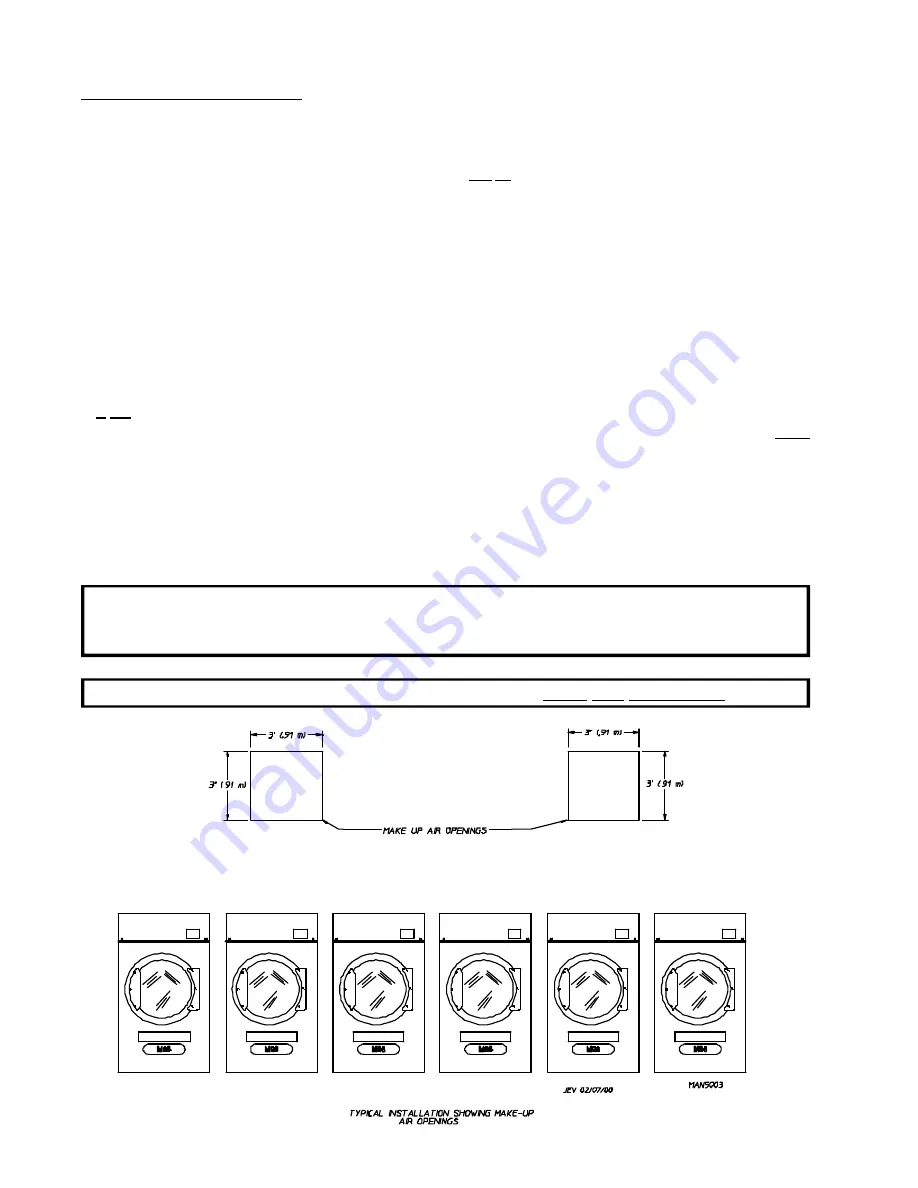
For a bank of six (6) dryers, two (2) unrestricted openings measuring 3 feet by 3 feet
(0.91 meters by 0.91 meters), 18 square feet (1.67 square meters) is acceptable.

Allowances 

must be

 made for remote or constricting passageways or where dryers are located at excessive

altitudes or predominantly low pressure areas.

IMPORTANT

: Make-up air 

must be

 provided from a source free of dry cleaning solvent fumes.

Make-up air that is contaminated by dry cleaning solvent fumes will result in
irreparable damage to the motors and other dryer components.

NOTE

: Component failure due to dry cleaning solvent fumes will VOID THE WARRANTY.

Summary of Contents for ML-96D

Page 1: ...your gas supplier call the firedepartment Installation and service must be performed by a qualifiedinstaller serviceagencyorthegas supplier AVERTISSEMENT Assurez vousdebien suivrelesinstructionsdonnéesdanscette noticepourréduireauminimumlerisque d incendieoud explosionoupourévitertout dommagematériel touteblessureoulamort Ne pas entreposer ni utiliser d essence ni d autresvapeursouliquidesinflamma...

Page 2: ...ations colors and material and to change or discontinue models Important For your convenience log the following information DATE OFPURCHASE ____________________________ MODEL NO __________________________________________ RESELLER SNAME _______________________________________________________________________________________ Serial Number s ____________________________________________________________...

Page 3: ...ERSINOPERATION DRYER S SHOULDNEVERBELEFTUNATTENDEDWHILEINOPERATION CAUTION FOR YOUR SAFETY DONOTDRYMOPHEADSINTHEDRYER DONOTUSEDRYERINTHEPRESENCEOFDRYCLEANINGFUMES WARNING UNDER NO CIRCUMSTANCES should the dryer door switches lint door switch heat safety circuit ever be disabled Caution Label all wires prior to disconnection when servicing controls Wiring errors can cause improper operation Attenti...

Page 4: ...played on the equipment and or specified in the installation manual included with the dryer Dryers must not be installed or stored in an area where it will be exposed to water or weather The wiring diagram for the dryer is located in the front electrical control box area DRYER MUST NEVER BE OPERATEDWITHOUTTHE LINTFILTER SCREEN IN PLACE EVENIFANEXTERNALLINTCOLLECTIONSYSTEMISUSED WARNING ...

Page 5: ...DryerEnclosureRequirements 13 D FreshAirSupply 14 E Exhaust Requirements 15 F ElectricalInformation 19 G GasInformation 22 H Preparation For Operation Start Up 25 I PreoperationalTests 26 J OperatingInstructions 27 K ShutDownInstructions 28 SECTION IV SERVICE PARTS INFORMATION 29 A Service 29 B Parts 29 SECTION V WARRANTY INFORMATION 30 A ReturningWarrantyCard s 30 B Warranty 30 C ReturningWarrant...

Page 6: ...TION VII PROCEDURE FOR FUNCTIONAL CHECK OF REPLACEMENT COMPONENTS 34 SECTION VIII DATA LABEL LOCATION INFORMATION 36 SECTION IX BURNER and BASKET TUMBLER LINT CHAMBER MANUAL RESET HI LIMIT INSTRUCTIONS 38 ...

Page 7: ...mber received and the number refused must be noted on the receipt 4 If you determine that the dryer was damaged after the trucker has left your location you should call the delivering carrier s freight terminal immediately and file a claim The freight company considers this concealed damage This type of freight claim is very difficult to get paid and becomes extremely difficult when more than a da...

Page 8: ...ly call your gas supplier from a neighbor s phone Follow the gas supplier s instructions f If you cannot reach your gas supplier call the fire department 4 Installation and service must be performed by a qualified installer service agency or gas supplier 5 Dryers must be exhausted to the outdoors 6 Although ADC produces a very versatile dryer there are some articles that due to fabric composition ...

Page 9: ...9 UNDER NO CIRCUMSTANCES should the dryer door switches lint door switch heat safety circuit ever be disabled WARNING PERSONAL INJURY or FIRE COULD RESULT 10 This dryer is not to be used in the presence of dry cleaning solvents or fumes 11 Remove articles from the dryer as soon as the drying cycle has been completed WARNING Articles left in the dryer after the drying and cooling cycles have been c...

Page 10: ...3 cm BASKET TUMBLER MOTOR 1 2 HP 0 373 kw BLOWER MOTOR 3 HP 2 238 kw DOOR OPENING DIAMETER 30 3 4 78 1 cm BASKET TUMBLER VOLUME 23 5 cu ft 0 67cu m DRYERS PER 20 40 CONTAINER 10 20 DRYERS PER 45 48 TRUCK 24 24 VOLTAGE AVAILABLE 208 460v 3ø 3 4w 50 60 Hz APPROX WEIGHT UNCRATED 878 lbs 453 6 kg APPROX WEIGHT CRATED 1 000 lbs 544 3 kg HEAT INPUT 350 000 btu hr 88 200 kcal hr AIRFLOW 2 700 cfm 76 5 cm...

Page 11: ...7 NOTE ADC reserves the right to make changes in specifications at any time without notice or obligation Specifications ML 96D ...

Page 12: ...llus No Description 1 Microprocessor Control Keyboard touch pad Panel Assembly controls 2 Control top access Door Assembly 3 Main Door Assembly 4 Lint Panel Assembly 5 Lint Door 6 Wire Diagram located behind control door 7 Top Console module Assembly ...

Page 13: ... Installation Label 6 Air Connection 7 Exhaust Transition Piece 8 Optional Exhaust Damper Assembly if damper option was purchased at time dryer order was placed the damper must be installed at time of dryer installation If damper option was purchased the damper is shipped inside the dryer basket tumbler 2 Dryer Rear View ...

Page 14: ...GA B149 2 M91 L P Gas or LATEST EDITION 1 The dryer must be installed on a sound level floor capable of supporting its weight Carpeting must be removed from the floor area that the dryer is to rest on IMPORTANT The dryer must be installed on noncombustible floors only 2 The dryer must not be installed or stored in an area where it will be exposed to water and or weather 3 The dryer is for use in n...

Page 15: ... 2 are at the rear base remove the back panel for access and two 2 are located in the bottom of the lint chamber To remove the two 2 bolts located in the lint chamber area remove the lint door To increase bearing life and improve efficiency the dryer should be tilted slightly to the rear The ML 96 is not provided with a back draft damper The damper is available as a dryer cost option If this dampe...

Page 16: ...ng the top console 1 Disconnect the ground wire A at the rear of dryer 2 Remove the six 6 sets of nuts and washers B holding the console module to base Located within control boxes 3 Open control door and control panel then disconnect the following a On the right side box disconnect the 4 pin and 2 pin plug Also remove the air connection at the union b On the left side box disconnect the drive and...

Page 17: ...ear of the dryer front The bulkhead facing must not be closed in ALL the way to the top of the dryer A 2 inch 5 08 cm clearance is required NOTE Bulkhead facing should not be installed until after dryer is in place Ceiling area must be located a minimum of 12 inches 30 48 cm above the top of the dryer NOTE When fire sprinkler systems are located above the dryers a minimum of 18 inches 45 72 cm abo...

Page 18: ...r the use of registers or louvers used over the openings this make up airmust beincreased by approximately thirty three percent 33 Make up air openings should not be located in an area directly near where exhaust vents exit the building It is not necessary to have a separate make up air opening for each dryer Common make up air openings are acceptable However they must be set up in such a manner t...

Page 19: ... angles instead The radius of the elbows should preferably be 1 1 2 times the diameter of the duct Excluding basket tumbler or dryer elbow connection in the exhaust duct run If more than two 2 elbows are used the cross section area of the ductwork must be increased in proportion to the number of elbows added ALL ductwork should be smooth inside with no projections from the sheet metal screws or ot...

Page 20: ...mn W C It is suggested that the ductwork from each dryer be a minimum of 16 inches 40 64 cm for horizontal runs with no more than one 1 elbow and 18 inches 45 72 cm for vertical runs with no more than three 3 elbows without exceeding 20 feet 6 1 meters excluding dryer connections and outside exhaust outlets If the duct exceeds 20 feet 6 1 meters or has numerous elbows the cross section area of the...

Page 21: ... prevent moisture and lint from escaping into the building Inspection doors should be installed at strategic points in the exhaust ductwork for periodic inspection and cleaning of lint from the ductwork NOTE When the exhaust ductwork passes through a wall ceiling or roof made of combustible materials the opening must be 2 inches 5 08 cm larger than the duct ALL the way around The duct must be cent...

Page 22: ...ize the cross section area of a square or rectangular duct must be increased twenty percent 20 for each additional 20 feet 6 1 meters The diameter of a round exhaust must be increased ten percent 10 for each additional 20 feet 6 1 meters Each 90º elbow is equivalent to an additional 36 feet 10 97 meters and each 45º elbow is equivalent to an additional 15 feet 4 57 meters IMPORTANT For extended du...

Page 23: ...ents It is your responsibility to have ALL electrical connections made by a properly licensed and competent electrician to assure that the electrical installation is adequate and conforms to local and state regulations or codes In the absence of such codes ALL electrical connections material and workmanship must conform to the applicable requirements of the National Electrical Code ANSI NFPA NO 70...

Page 24: ...l area behind the control door In the case of 208 VAC or 240 VAC the supply voltage must match the electric service specifications of the data label exactly IMPORTANT The wire size must be properly sized to handle the related current WARNING 208 VAC and 240 VAC ARE NOT THE SAME Any damage done to dryer components due to improper voltage connections will automatically VOID THE WARRANTY NOTE ADC res...

Page 25: ...rs they must be jumped out with no 4 copper wire and securely clamped to bare metal at both ends IMPORTANT For personal safety and proper operation the dryer must be grounded For proper operation of the microprocessor controller computer an earth zero ground is required NOTE Grounding via metallic electrical conduit pipe IS NOT RECOMMENDED 4 Electrical Connections NOTE A wire diagram is located in...

Page 26: ...ause irreparable damage to the gas valve which will VOID THE WARRANTY WARNING FIRE or EXPLOSION COULD RESULT 1 Gas Supply The gas dryer installation must meet the American National Standard National Fuel Gas Code ANSI Z223 1 LATEST EDITION or in Canada the Canadian Installation Codes CAN CGA B149 1 M91 Natural Gas or CAN CGA B149 2 M91 L P Gas or LATEST EDITION as well as local codes and ordinance...

Page 27: ...stent 10 5 inches 26 1 mb water column There is no regulator or regulation provided in an L P dryer The water column pressuremust be regulated at the source L P tank or an external regulator must be added to each dryer Natural Gas 10 0 1935 4 9149 mm Liquid Propane Gas 33 0 1130 2 8702 mm TYPE OF GAS L P Conversion Kit Part Number MODEL NUMBER BTU Per Hour Rating kcal hr Rating Natural Liquid Prop...

Page 28: ...ng supplied The dryer is provided with a 1 inch N P T inlet pipe connection located at the right side of the base of the dryer The minimum pipe size supply line to the dryer is 1 inch N P T For ease in servicing the gas supply line of each dryer must have its own shutoff valve The size of the main gas supply line header will vary depending on the distance this line travels from the gas meter or in...

Page 29: ...alified professional It is important that gas pressure regulators meet applicable pressure requirements and that gas meters be rated for the total amount ofALL the appliance BTUs being supplied IMPORTANT The dryer and its individual shutoff valve must be disconnected from the gas supply piping system during any pressure testing of that system at test pressures in excess of 1 2 psig 3 5 kPa NOTE Th...

Page 30: ...ts in the clockwise CW direction Additionally check the direction of the blower motor impellor fan to ensure the impellor fan rotates in the clockwise CW position as viewed from the front If it is the phasing is correct If the phasing is incorrect reverse two 2 of the leads at L1 L2 or L3 of the power supply connections made to the dryer IMPORTANT Dryer blower motor impellor fan as viewed from abo...

Page 31: ...ET COATING The basket tumbler is treated with a protective coating We suggest dampening old garments or cloth material with a solution of water and non flammable mild detergent and tumbling them in the basket tumbler to remove this coating J OPERATING INSTRUCTIONS NOTE Before attempting to start the dryer make sure the main door is closed and the lint drawer is securely in place 1 To start the dry...

Page 32: ...ght emitting diode L E D display will return to READY at which time a new cycle selection can be made K SHUT DOWN INSTRUCTIONS If the dryer is to be shut down taken out of service for a period of time the following must be performed 1 Discontinue electrical power to the dryer either at the external disconnect switch or the circuit breaker 2 Discontinue the gas supply a SHUT OFF external gas supply...

Page 33: ...erial numberso that your inquiry is handled in an expeditious manner B PARTS 1 Replacement parts should be purchased from the reseller from whom theADC equipment was purchased If the reseller cannot be contacted or is unknown contact theADC Parts Department for a reseller in your area Parts may also be purchased directly from the factory by calling theADC Parts Department at 508 678 9000 or you ma...

Page 34: ...whom you purchased the equipment and request dryer warranty form If the reseller cannot be contacted or is unknown warranty information can be obtained from the factory by contacting the ADC Warranty Department at 508 678 9000 NOTE Whenever contacting the ADC factory for warranty information be sure to have the dryer s model numberand serial numberavailable so that your inquiry can be handled in a...

Page 35: ...t Damage claims are the responsibility of the shipper IMPORTANT No replacements credits or refunds will be issued for merchandise damaged in transit 5 ALL returns should be shipped to the ADC factory in such a manner that they are insured and a proof of delivery can be obtained by the sender 6 Shipping charges are not the responsibility of ADC ALL returns should be prepaid to the factory Any C O D...

Page 36: ...me intervals shown are for average usage which is considered six 6 to eight 8 operational running hours per day SUGGESTED CLEANING SCHEDULE EVERY LOAD Clean the lint screen after every load A clogged lint screen will cause poor dryer performance The lint screen is located behind the lint door in the base of the dryer Open the lint door brush the lint off the lint screen and remove the lint Inspect...

Page 37: ...t circuit safety switches or thermostats NOTE When cleaning the dryer cabinets avoid using harsh abrasives A product intended for the cleaning of appliances is recommended B ADJUSTMENTS 7 DAYS AFTER INSTALLATION and EVERY 6 MONTHS THEREAFTER Inspect bolts nuts screws bearing setscrews and nonpermanent gas connections unions shutoff valves orifices and grounding connections Motor and drive belts sh...

Page 38: ...pen as long as there is a call for heat The DSI module will LOCKOUT if the gas burner flame is not sensed at the end of the trial for ignition period The trial for ignition period willbe repeated for a total of three 3 retries trials the initial try and two 2 more retries trials If the flame is not sensed at the end of the third retry trial inter purge period of 30 seconds the DSI module will LOCK...

Page 39: ...The burner flame should now be established e With the burner flame on remove the flame sensor wire from the FS terminal of the DSI module f The burner flame must shut off and the ignition module must lockout with the DSI module s indicator light red g Stop the drying cycle with the flame sensor wire still removed restart the drying cycle h The ignition module must proceed through the prepurge with...

Page 40: ...ryer Corporation certain information is required to insure proper service parts information from American Dryer Corporation This information is on the data label located to the left side panel wall area behind the control door When contacting American Dryer Corporation please have the model numberand serial numberavailable ...

Page 41: ... options on your particular model 4 TYPE OF HEAT This describes the type of heat for your particular dryer gas natural gas or steam 5 HEAT INPUT for GAS DRYERS This describes the heat input in British Thermal Units per Hour BTUH 6 ORIFICE SIZE for GAS DRYERS Gives the number drill size used 7 ELECTRIC SERVICE This describes the electric service for your particular model 8 GAS MANIFOLD PRESSURE for...

Page 42: ...rror code described above along with an audio indication If the drum temperature is above 100 F 38 C the dryer will continue to run with no heat for 3 minutes or until the drum temperature has flattened below 100 F 38 C The STOP CLEAR button on the Phase 6 keyboard touch pad mustbe pressed to clear the error condition The open manual reset hi limit thermostatmust be reset manually prior to the sta...

Page 43: ...ADC 113125 1 02 16 00 10 2 12 08 00 10 3 03 09 01 25 ...

Reviews: