background image

22

b.  Gas Connections:

Inlet connection

3/4” inch N.P.T.

Inlet supply size

3/4” inch N. P.T.

Btu/hr input (per dryer)

200,000

1.  Natural Gas

Regulation is controlled by the dryer’s gas valve’s internal regulator.  Incoming supply pressure

must be

 consistent between 6 and 12 inches water column pressure.

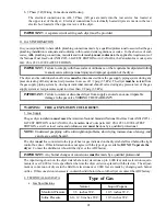
2.  Liquid Propane (L.P.) Gas

Dryers made for use with L.P. gas have the gas valve’s internal pressure regulator blocked open so
that the gas pressure 

must be

 regulated upstream of the dryer.  The pressure measured at each gas

valve pressure tap 

must be

 a consistent 11 inch water column.  There is no regulator or regulation

provided in an L.P. dryer.  The water column pressure must be regulated at the source (L.P. tank)
or an external regulator 

must be

 added to each dryer.

*D.M.S. (Drill Material Size) equivalent are as follows:

Natural Gas.........................#29 = .1360”
Liquid Propane Gas..............#47 = .0785”

3.  Piping and Connections

ALL

 components and materials 

must conform

 to National Gas Code specifications.  It is important that

gas pressure regulators meet applicable pressure requirement and that gas meters be rated for the total
amount of 

ALL

 the appliance BTU’s being supplied.

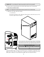
The dryer is provided with a 3/4” N.P.T. inlet pipe connection located at the right side of the base of the
dryer.  The minimum pipe size (supply line) to the dryer is 3/4” N.P.T.  For ease servicing, the gas supply
line of each dryer 

must have

 its own shut-off valve.

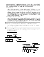
The size of the main gas supply line (header) will vary depending on the distance this line travels from
the gas meter or, in the case of L.P. (liquid propane) gas, the supply tank, other gas-operated appliances
on the same line, etc.  Specific information regarding supply line size 

should be

 determined by

the gas supplier.

NOTE:

Undersized gas supply piping can create a low or inconsistent pressure which will result in erratic
operation of the burner ignition system.

Type of Gas

L.P.

Conversion

Kit Part
Number

Natural

Liquid Propane

Model

Number

BTU Per

Hour

Rating

Qty.

D.M.S.*

Part

Number

Qty.

D.M.S.*

Part

Number

ML79 WW

200,000

4

#29

4

4

#47

140805

881231

Summary of Contents for Wet Wash ML-79

Page 1: ... you cannot reach your gas supplier call the fire department Installation and service must be performed by a qualified installer service agency or the gas supplier AVERTISSEMENT Assurez vous de bien suivre les instructions données dans cette notice pour réduire au minimum le risque d incendie ou d explosion ou pour éviter tout dommage matériel toute blessure ou la mort Ne pas entreposer ni utilise...

Page 2: ...prominent location near the dryer American Dryer Corporation products embody advanced concepts in engineering design and safety If this product is properly maintained it will provide many years of safe efficient and trouble free operation ONLY qualified technicians should service this equipment OBSERVEALL SAFETY PRECAUTIONS displayed on the equipment or specified in the installation operator s man...

Page 3: ...ED IF NEAR DRYERS IN OPERATION DRYER S SHOULD NEVER BE LEFT UNATTENDED WHILE IN OPERATION CAUTION FOR YOUR SAFETY DO NOT DRY MOP HEADS IN THE DRYER DO NOT USE DRYER IN THE PRESENCE OF DRY CLEANING FUMES WARNING UNDER NO CIRCUMSTANCES should the door switch or the heat circuit devices ever be disabled Caution Label all wires prior to disconnection when servicing controls Wiring errors can cause imp...

Page 4: ...the equipment and or specified in the installation operator s manual included with the dryer Dryers must not be installed or stored in an area where it will be exposed to water and or weather The wiring diagram for the dryer is located in the front electrical control box area DRYER MUST NEVER BE OPERATED WITHOUT THE LINT FILTER SCREEN IN PLACE EVEN IF AN EXTERNAL LINT COLLECTION SYSTEM IS USED WAR...

Page 5: ...king Setting Up 10 C Dryer Enclosure Requirements 11 D Make Up Air Requirements 12 E Exhaust Requirements 14 F Electrical Information 18 G Gas Information 21 H Air Information 25 I Preparation For Operation Start Up 26 J Preoperational Tests 27 K Preoperational Instructions 28 L Shut Down Instructions 28 SECTION IV 29 SERVICE PARTS INFORMATION A Service 29 B Parts 29 SECTION V 30 WARRANTY INFORMAT...

Page 6: ... ROUTINE MAINTENANCE A Cleaning 32 SECTION VII 34 TROUBLESHOOTING SECTION VIII 41 TECHNICAL INFORMATION SECTION IX 42 PROCEDURE FOR FUNCTIONAL CHECK OF REPLACEMENT COMPONENTS AQUATEX HUMIDITY SENSOR INSTRUCTIONS 44 ...

Page 7: ...cepted but the number received and the number refused must be noted on the receipt 4 If you determine that the dryer was damaged after the trucker has left your location you should call the delivering carrier s freight terminal immediately and file a claim The freight company considers this concealed damage This type of freight claim is very difficult to get paid and becomes extremely difficult wh...

Page 8: ...all your gas supplier from a neighbor s phone Follow the gas supplier s instructions f If you cannot reach your gas supplier call the fire department 4 Installation and service must be performed by a qualified installer service agency or gas supplier 5 Dryer s must be exhausted to the outdoors 6 Although ADC produces a very versatile machine there are some articles that due to fabric composition o...

Page 9: ...itches the lint drawer switch or the heat safety circuit ever be disabled WARNING PERSONAL INJURY or FIRE COULD RESULT 10 This dryer is not to be used in the presence of dry cleaning solvents or fumes 11 Remove articles from the dryer as soon as the drying cycle has been completed WARNING Articles left in the dryer after the drying and cooling cycles have been complete can create a fire hazard 12 ...

Page 10: ...1 200 cfm 33 98 cmm Inlet Pipe Size 3 4 1 91 cm Voltage Available 208 460v 10 30 50 60 Hz Approx Weight Uncrated 721 lbs 327 kg Approx Weight Crated 771 lbs 349 7 kg Airflow 1 200 cfm 33 98 cmm SECTION II SPECIFICATIONS COMPONENT IDENTIFICATION A SPECIFICATIONS Gas Electric Minimum of 3 4 pipe must be supplied to the gas inlet for each dryer Shaded areas are stated in metric equivalents IMPORTANT ...

Page 11: ...7 Specifications ML 79 WET WASH ...

Page 12: ... access Door Assembly 3 Main Door Assembly Left hand shown 4 Lint Compartment Area lint screen located behind door 5 Data Label and Installation Label located behind control service door 6 Emergency Stop B COMPONENT IDENTIFICATION 1 Dryer Front View ...

Page 13: ... floor area that the dryer is to rest on 2 The dryer must not be installed or stored in an area where it will be exposed to water or weather 3 The dryer is for use in noncombustible locations 4 Provisions for adequate air supply must be provided as noted in this manual Refer to Fresh Air Supply insection D 5 Clearance provisions must be made from combustible construction as noted in this manual Re...

Page 14: ...ld be titled slightly to the rear The basket tumbler is supported during shipping by a wooded block REMOVE THIS BLOCK BEFORE STARTING THE DRYER IMPORTANT For microprocessor computer models this wooden block must be removed before connecting power to the dryer or irreparable damage to the basket tumbler will result The lint coops of ALL MW 79 dryers are supported during shipping by a bracket REMOVE...

Page 15: ...st not be closed in all the way to the top of the dryer A one 1 inch clearance is required NOTE Allowances must be made for opening the control door Dryers may be positioned side wall to side wall However a 1 16 minimum allowance must be made for opening and closing of the control door and the lint door It is suggested that the dryer be positioned about two 2 feet away from the nearest obstruction...

Page 16: ...yer is operating it draws in room air heats it passes this air through the basket tumbler and exhausts it out of the building Therefore the room air must be continually replenished from the outdoors If the make up air is inadequate drying time and efficiency will be adversely affected Ignition problems and sail switch fluttering problems may result as well as premature motor failure from overheati...

Page 17: ...he make up air is distributed equally to ALL of the dryers EXAMPLE For a bank of four 4 dryers two 2 unrestricted openings measuring 2 feet by 1 1 2 feet 6 square feet is acceptable Allowances must be made for remote or constricting passageways or where dryers are located at excessive altitudes or predominantly low pressure areas IMPORTANT Make up airmust beprovidedfromasourcefreeofdrycleaningsolv...

Page 18: ...ion from the weather no more than two 2 elbows should be used in the exhaust duct run If more than two 2 elbows are used the cross sectional area of the duct work must beincreased ALL duct work should be smooth inside with no projections from sheet metal screws or other obstructions which will collect lint When adding ducts the duct to be added should overlap the duct to which it will connected AL...

Page 19: ...use of 90º turns in the ducting be avoided use 30º or 45º angles instead The shape of the exhaust duct work is not critical so long as the minimum cross section area is provided IMPORTANT Minimum duct size for dryer is 10 inches for a round duct or 9 x 9 for a square duct The duct size must not be reduced anywhere down stream of the dryer IMPORTANT Exhaust back pressure measured by a manometer at ...

Page 20: ...lbow is equivalent to an additional fifteen 15 feet IMPORTANT For extended duct work runs the cross section area of the duct work can only be increased to an extent Maximum proportional duct work runs cannot exceed fifteen 15 feet more than the original limitations of the maximum limit noted in this manual a professional heating venting air conditioning HVAC firm should be consulted for proper ven...

Page 21: ... up through the roof it should be protected from the weather by using a 180º turn to point the opening downward In either case allow at least twice the diameter of the duct between the duct opening and the nearest obstruction IMPORTANT DO NOT use screens or caps on the outside of the exhaust duct work IMPORTANT For extended duct work runs the cross section area of the duct work can only be increas...

Page 22: ...ervice connections NOTE The use of aluminum wire will VOID THE WARRANTY NOTE Wiring diagrams are afficed to the inside at the top front control door and to the rear upper back guard panel F ELECTRICAL INFORMATION 1 ELECTRICAL REQUIREMENTS It is your responsibility to have ALL electrical connections made by a properly licensed and component electrician to assure that the electrical installation is ...

Page 23: ...SA C22 1 1990 or LATEST EDITION The ground connection may be to a proven earth ground at the location service panel For added personal safety when possible it is suggested that a separate ground wire no 18 minimum be connected from the ground connection of the dryer to a grounded cold water pipe DO NOT ground to a gas pipe or hot water pipe The grounded cold water pipe must have a metal to metal c...

Page 24: ...ox located at the upper left area of the dryer Single Phase 1Ø Electrical Leads Black and Positive White and Neutral Green and Ground or L2 If local codes permit power to the dryer can be made by the use of a flexible U L listed power cord or pigtail wire size must conform to rating of dryer or the dryer can be hard wired directly to the service breaker panel In both cases a strain relief must be ...

Page 25: ...or less than 1 2 psig 3 5 kPa IMPORTANT Failure to isolate or disconnect dryer from supply as noted can cause irreparable damage to the gas valve VOIDING THE WARRANTY WARNING FIRE or EXPLOSION COULD RESET 1 Gas Supply The gas dryer installation must meetthe American National Standard National Fuel Gas Code ANSI Z223 1 LATEST EDITION or in CANADA the Canadian Gas Codes parts 1 2 CSA C22 1 1990 LATE...

Page 26: ...orm to National Gas Code specifications It is important that gas pressure regulators meet applicable pressure requirement and that gas meters be rated for the total amount of ALL the appliance BTU s being supplied The dryer is provided with a 3 4 N P T inlet pipe connection located at the right side of the base of the dryer The minimum pipe size supply line to the dryer is 3 4 N P T For ease servi...

Page 27: ...corner of the dryer The ground connection is made to the copper lug also provided in this box To gain access to the service box and contactor the service box cover must be removed 2 ELECTRICALLY Heated Models Only The only electrical input connections to the dryer are the 3 phase 3Ø power leads L1 L2 L3 and sometimes neutral and ground Single phase power for the control circuit and for any single ...

Page 28: ... of each dryer IMPORTANT Pipe joint compounds that resist the action of natural gas and L P gas must be used IMPORTANT Test ALL connections for leaks by brushing on a soapy water solution liquid detergent works well WARNING NEVER TEST FOR LEAKS WITH A FLAME ALL components and materials must confirm to National Gas Code specifications It is important that gas pressure regulators meet applicable pre...

Page 29: ...TE Drain bowls with manual drain to keep accumulated liquids below element Liquid will be carried downstream if it reaches the element Replace element when plugged A Air Requirements 1 The air supply required to operate this dryer correctly is regulated at 40 p s i Any deviation from this may cause damage to the outlet humidity sensor B Air Connection 1 The air connection to the dryer is of 1 8 N ...

Page 30: ...C MODELS The sail switch damper assembly was installed and adjusted at the factory prior to shipping However each sail switch adjustment must be checked to assure that this important safety control is functioning 5 GAS MODELS Be sure that ALL gas shut off valves are in the open position 6 Be sure ALL side and base panels are on the dryer 7 Check ALL service doors to assure that they are closed and...

Page 31: ...yers are equipped with a direct spark ignition DSI system which has internal diagnostics If ignition is not established the heat circuit in the DSI module will lock out until it is manually reset To reset the DSI system open and close the main door and restart the dryer b A gas pressure test should be taken at the gas valve pressure tap of each dryer to assure that the water column pressure is cor...

Page 32: ... models only While the dryer is operating check to see if the blower wheel impellor and fan should spin in the clockwise direction If it is the phasing is correct If the phasing is incorrect reverse two 2 of the three 3 leads at connections L1 L2 L3 of the power supply to the dryer IMPORTANT If the blower wheel impellor and fan is rotating in the wrong direction this will not only drastically redu...

Page 33: ...correct model and serial numbers so your inquiry is handled in a timely manner B PARTS 1 Replacement parts should be purchasedfrom the distributor that the ADC equipment was purchased If the distributor cannot be contacted or is unknown contact the ADC Parts Department for a distributor in your area Parts may also be purchased directly from the factory by calling the ADC Parts Department at 508 67...

Page 34: ...om the factory by contacting then ADC Warranty Department at 508 678 9000 NOTE Whenever contacting the ADC factory for warranty for warranty information be sure to have the dryer s model numberand serial numberavailable so that your inquiry can be handled in an expeditious manner C RETURNING WARRANTY PARTS ALL dryer or parts warranty claims or inquires should be addressed to the ADC Warranty Parts...

Page 35: ...nts credits or refunds will be issued for merchandise damaged in transit 5 ALL returns should be shipped to the ADC factory in such a manner that they are insured and a proof of delivery can be obtained by the sender 6 Shipping charges are not the responsibility of ADC ALL returns should be prepaid to the factory Any C O D or COLLECT returns will not be accepted IMPORTANT No replacements credits o...

Page 36: ...N OF LINT CAN CREATE A POTENTIAL FIRE HAZARD WARNING KEEP DRYER AREA CLEAR AND FREE FROM COMBUSTIBLE MATERIALS GASOLINE and OTHER FLAMMABLE VAPORS and LIQUIDS NOTE REMOVE POWER FROM THE MACHINE BEFORE PERFORMING ANY MAINTENANCE IN THE MACHINE cleaning the lint drawers and both steam coil lint screens are the only exceptions NOTE Suggested time intervals shown are for average usage which is conside...

Page 37: ...ve lint from gas valve burner area with a dusting brush or vacuum cleaner attachment NOTE To prevent damage avoid cleaning and or touching the Hot Surface Ignitor Remove lint accumulation from inside 6 MONTHS Inspect and remove lint accumulation in customer furnished exhaust duct work system and from dryers internal exhaust ducting NOTE THE ACCUMULATION OF LINT IN THE EXHAUST DUCT WORK CAN CREATE ...

Page 38: ...rson in making repairs WARNING ALL SERVICE AND TROUBLESHOOTING SHOULD BE PERFORMED BY A QUALIFIED PROFESSIONAL OR SERVICE AGENCY WARNING WHILE MAKING REPAIRS OBSERVE ALL SAFETY PRECAUTIONS DISPLAYED ON THE DRYER OR SPECIFIED IN THIS MANUAL TABLE OF CONTENTS MICROPROCESSOR COMPUTER MODELS ITEM PAGE No L E D Display A 35 Drive motor does not operate B C 35 Microprocessor controller display reads dFS...

Page 39: ...otor d Basket tumbler is binding check for obstruction D Microprocessor controller computer display reads dFSL continuously and the buzzer tone sounds every 30 seconds 1 Fault in microprocessor heat sensing circuit a Blown dFSL 1 8 amp fuse on the microprocessor computer b Failed microprocessor temperature sensor c Failed microprocessor controller d Broken wire or connection somewhere between the ...

Page 40: ...or controller computer and the microproces sor temperature sensor 2 Loose dSFL 1 8 amp fuse on the microprocessor controller computer K Dryer stops during a cycle microprocessor controller computer buzzer tone sounds for 5 seconds and then the L E D display returns to FILL 1 Loose connection somewhere in the main power circuit to the microprocessor controller computer 2 Failed arc suppressor A S b...

Page 41: ...tactor 1 Failed microprocessor controller computer O No heat voltage is confirmed at heating unit i e gas model DSI module or electric oven contactor GAS MODELS 1 Fault in DSI ignition system a Ignitor sparks but no ignition and module locks out RED indicator stays on 1 Ignitor probe assembly is out of adjustment or has failed 2 Severe air turbulence 3 Failed DSI module 4 Failed gas valve b Ignito...

Page 42: ... gas pressure must be between 3 5 and 4 inches of water column L P gas pressure must be between 10 5 and 11 inches of water column b Poor air and gas mixture too much gas or not enough air at burner yellow or poor flame pattern 1 Not enough make up air 2 Restriction in exhaust 3 Gas pressure too high 4 Impellor and fan rotating in the wrong direction 3 phase models 5 Burner orifice size D M S too ...

Page 43: ...ng out still damp 1 Percent of dryness dryness level of cycle selected is too low 2 A and B factors not set correctly or B factor has to be adjusted for adverse location conditions S Main burners are burning with a yellow flame for gas models only 1 Poor air and gas mixture too much gas or not enough air at burner a Not enough make up air b Restriction in exhaust c Gas pressure too high d Blower a...

Page 44: ...p on blower and fan b Failed blower and fan 3 Loose basket tumbler tie rod 4 Failed tumbler support 5 Loose motor mount 6 Failed idler or basket tumbler bearings 7 V belts too tight or too loose 8 Tumbler bearing set screws are loose 9 Failed motor bearings ...

Page 45: ... heat gas electric or steam 2 SERIAL NUMBER The serial number allows ADC to gather information on your particular dryer 3 MANUFACTURING CODE NUMBER The manufacturing code number is issued by ADC and describes all possible options on your particular model 4 TYPE OF HEAT Describes the type of heat gas natural or L P steam or electric 5 HEAT INPUT For gas dryers describes the heat input in British th...

Page 46: ...cement microprocessor computer board reestablish power to the dryer b Start the drying cycle c Verify that the motors and the heat indicator dots in the microprocessor computer L E D display are on Refer to the illustration below d Verify that the motors heat and door indicator lights on the back side of the microprocessor computer board are lit ...

Page 47: ...e purge time d The module s indicator light will then turn green The gas valve will be energized and the ignitor probe will spark for approximately 8 seconds The burner flame should now be estab lished e With the burner flame on remove the flame sen sor wire from the FS terminal of the DSI mod ule f The burner flame must shut off and the igni tion module must lock out with the DSI module s indicat...

Page 48: ...r 2 Install sensor by running the sensor through the hole in the outer top of dryer See figure 1 3 Insert rubber grommet that is on humidity sensor wire in hole on outer top 4 Place humidity sensor in grommet as in figure 2 The humidity sensor must be free from all obstruc tions in order for proper operation See figure 2 figure 1 figure 2 ...

Page 49: ...ADC 113026 1 07 29 99 25 2 12 08 00 10 ...

Reviews: