background image

6

Class 3 Compressor Owner’s Manual

Return Line

Pressure
Line

FAN

GND

CPRSR

SPD CTRL

PRESSURE

SWITCH

LINE

MOTOR

HYDRAULIC

MANIFOLD

COMPRESSOR (12V INPUT)

GROUND

SPEED CONTROL

C

B

A

C

B

A

SHD-43 Installation

Pump Assembly: 

The pump assembly may either be installed directly

on the PTO or as an optional method, may be

driven by a driveline from the PTO.  Pump

manufacturers provide specific installation

information for their products and should be

consulted if questions arise.  

PTO Assembly: 

Check with the PTO manufactures representative

for specific instructions regarding your particular

make, model, and year of vehicle.  As some trucks

may require modification of the transmission cross

member and the exhaust system, the

manufacturer’s instructions should be followed to

insure proper installation of the PTO.  

Compressor Assembly:

Prepare the mounting location of the compressor

by locating and drilling four (4) holes, 7/16”

diameter as per the mounting pattern of the air

compressor base.  Using four (4) 3/8” x 1.25 GR-5

cap screws, 3/8” flat washers, and 3/8” nyloc nuts,

secure the compressor in place.  The compressor is

air cooled, and must have a clean supply of

cooling air to the fan with minimum restrictions.

Adequate space must be provided for proper

circulation of air.  

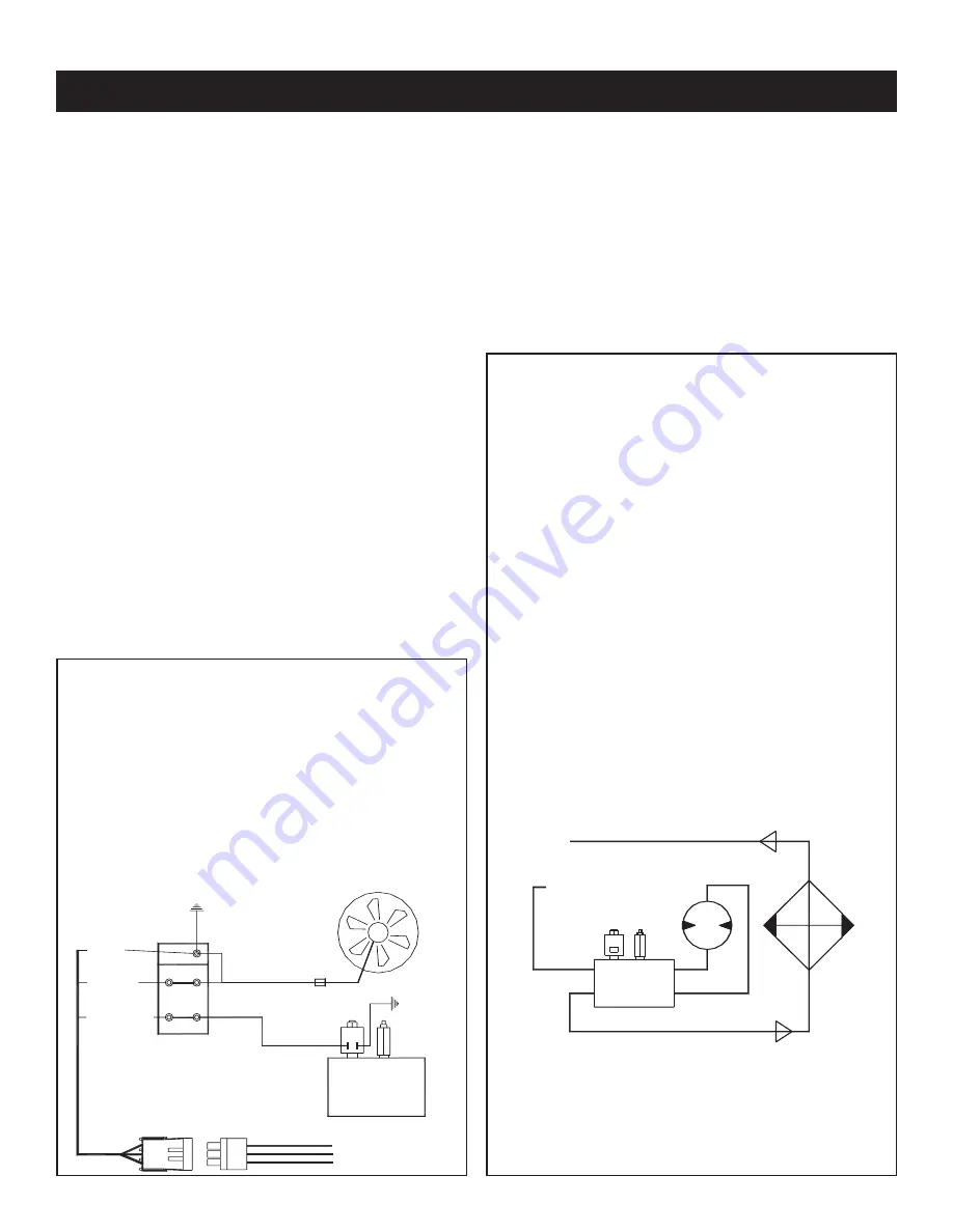
Electrical Connections: 

From the air pressure switch there are two (2) wires,

red and black, running to the outside of the

compressor housing.  Connect the black wire to the

vehicle frame or other suitable ground.  Mount a

single throw toggle switch in a convenient location

and connect the red wire from the compressor to

this switch.  Connect the other switch terminal to a

fuse holder and then to a 12-volt power supply.  A

third wire is required from the air compressor switch

when connecting the speed control into the

system. (See drawing below)  

Electric speed control: 

An optional electric or electronic speed control

must be used to maintain proper operating speed

of the air compressor.  The engine speed control will

automatically increase from idle to preset speed

when engaged and decrease when disengaged.

The electric cable pull speed control American

Eagle P/N 25740 is used on most gasoline engines.

The electronic speed controls are used only on Ford

7.3 and 6.0L diesel engines.  Proper installation

instructions are provided with each system.

Hydraulic System: 

The hydraulic system consists of the pump, oil

reservoir, filters and hoses.  Installed on the

compressor is a valve block assembly that controls

the flow to the hydraulic motor.  To this block, a 1/2”

high-pressure hose must be attached.  This hose

comes from the hydraulic pumps pressure side.  A

3/4” minimum low-pressure return line is connected

to the oil cooler outlet and is routed to the oil

reservoir. American Eagle recommends a sufficient

sized reservoir be provided which includes the

proper suction and return filters.  The cooler on the

compressor is designed and sized to cool the air

compressor efficiently.  An auxillary oil cooler is

required when additional hydraulically operated

equipment are added to the hydraulic system.

Pressure on the return line exceeding 200 PSI can

and will cause damage to the filter, cooler, and

components of the compressor hydraulic system. 

Summary of Contents for SHD 43

Page 1: ...x 641 923 9099 www americaneagleacc com Model V360 Compressor Model SUH 43 Compressor Model SHD 43 Compressor Manual Part No 40983 Last Revision 11 19 09 Subject to Change without Notification 2009 Am...

Page 2: ...Class 3 Compressor Manual Revisions Date of Revision Description of Revision Section Revised...

Page 3: ...ase Group Straight Shaft 9 Cylinder Group 10 Head Group 11 Head Options 12 Optional Head Unloader 13 Flywheel Options 14 Clutch Options 15 SUH 43 Compressor Assembly 16 SHD 43 Compressor Assembly 17 H...

Page 4: ...Introduction components and parts deemed necessary for product improvement or commercial production purposes This right is kept with no requirement or obligation for immediate mandatory updating of th...

Page 5: ...tal engagement of the tool can cause serious injury Before performing any maintenance on the compressor place a warning tag on the hydraulic power source or disconnect the hoses from the compressor mo...

Page 6: ...ing 12 VDC Solenoid Control Valve All Steel Plumbing W JIC Fittings 165 Sq In 300 BTU Cooler 361 CFM 12 Volt Cooler Fan 6061 Aluminum Manifold Direct Drive Coupling Air Pressure Control Valve SHD 43 D...

Page 7: ...nut on the cable end make the adjustment and retighten the jam nut For electronic operated speed controls adjust speed adjustment screw as needed to set RPM For setting engine RPM through the chassis...

Page 8: ...ystems and the general cleanliness of the equipment Proper fluids according to the specifications are required USE AE SYNTHETIC COMPRESSOR OIL P N C0087 COMPRESSOR CRANKCASE CAPACITY IS 1 QUART Servic...

Page 9: ...bolts to 31 Ft lbs torque doing the 2 long center bolts first and the 4 short bolts last After five hours of use re torque bolts to 31 Ft lbs Cylinder Assembly Torque Value 20 FT LBS Procedure After...

Page 10: ...switch in a convenient location and connect the red wire from the compressor to this switch Connect the other switch terminal to a fuse holder and then to a 12 volt power supply A third wire is requir...

Page 11: ...tting at 115 psi minimum 120 psi maximum 3 Cycle compressor to verify correct settings 4 For questions about this procedure please contact Stellar Customer Service Kick On Step 2 Pressure Setting Adju...

Page 12: ...K 8 5821 BEARING CARRIER OIL PUMP V360 V480 1 27 C0052 PORT PLATE MACHINED 1 9 5822 GASKET BEARING CA 1 3 6 X 9 1 0 N I P L L O R 9 0 2 2 2 8 2 5 5 1 0 0 8 4 V R E I R R 10 C6271 FRONT PL 1 L L A M S...

Page 13: ...5 1 1 8 4 0 7 6 M L E N O C G N I R A E B 6 5 8 0 C 6 1 1 S O 0 6 3 0 8 4 T F 0 8 4 V R E I R R A C G N I R A E B 2 8 4 3 2 7 1 1 0 1 0 7 6 M L P U C G N I R A E B 3 6 1 1 C 8 1 5 H S 5 7 0 X 8 1 1 3...

Page 14: ...1 0 2 C 3 1 0 6 3 V R E D N I L Y C 5 4 0 0 C 4 2 N I P N O T S I P 9 6 5 1 C 5 4 2 6 0 0 0 5 N N I P N O T S I P G N I R P A N S 3 7 2 6 C 6 2 R E D I V I D X E L F 0 6 3 V L I O G N I R 6 3 0 6 7 4...

Page 15: ...7 5828 WASHER LONG HD BOLT BRASS 1 8 C1582 BOLT 3 00 HEAD SACKED 2 9 C1586 CAP SCR 0 38 16X1 75 SH HEAD BOLT 4 1 N E E R C S R E T L I F 7 9 2 0 C 0 1 1 M A O F R E T L I F 5 1 7 0 C 1 1 1 R E N I A T...

Page 16: ...ir Cooled Imbedded Filter 3 4 Threaded NPT Discharge with Head Unloader Ports C1631 Aluminum Water Cooled Imbedded Filter 3 4 Threaded NPT Discharge 15195 Cast Iron Air Cooled 3 4 Threaded Intake Port...

Page 17: ...6 0220 CAP SCR 0 25 20 X 1 50 HHGR5 5 2 22599 GASKET UNLOADER 1 7 22596 CAP SCR 0 38 16X4 00 SH HEAD BOLT 1 3 22593 PISTON HEAD UNLOADER CPRSR 2 8 C0040 WASHER HD BOLT STL 1 4 22598 O RING 2 116 HEAD...

Page 18: ...14 Class 3 Compressor Owner s Manual Flywheel Options 22997 12 B GROOVE 22838 14 DUAL GROOVE...

Page 19: ...rawings 15 Clutch Options C4705 7 DUAL V C4704 6 DUAL V C4723 6 8 GROOVE SERPENTINE 8198 6 8 GROOVE 24V SERPENTINE 5793 6 8 GROOVE 12V SERPENTINE C4775 7 SINGLE V 5774 6 6 GROOVE 12V SERPENTINE C4762...

Page 20: ...SS ELL 90 DEG A C 2 12 C4692 FTG 0 75 JIC ML NPT 12CTX 90 DEG EL 1 1 R O S S E R P M O C S E R P H C T I W S 3 6 8 0 C 3 1 1 0 0 2 1 X 3 6 0 E S O H 6 9 1 5 2 4 1 4 2 4 0 4 1 T P N M F 4 1 L M 8 1 T P...

Page 21: ...D 5019 4 14 B0682 BRKT COOLER MOUNT SHD60 1 45 13529 FILTER AIR SHD60 1 15 0351 CAP SCR 0 38 16X1 00 HHGR5 6 46 0482 CAP SCR 0 25 20 X 3 00 HHGR5 2 16 C1129 COOLER OIL 1 47 0333 NUT 0 25 20 HHGR5 NYL...

Page 22: ...18 Class 3 Compressor Owner s Manual Hydraulics Electrical SHD 43 Control Kit FAN GND CPRSR SPD CTRL PRESSURE SWITCH LINE MOTOR HYDRAULIC MANIFOLD COMPRESSOR 12V INPUT GROUND SPEED CONTROL C B A C B A...

Page 23: ...Hydraulics Electrical 19 PN 30533 PN 30532 Typical Hydraulic Circuit for Single Stage Pump with Multiple Components Typical Hydraulic Circuit for Tandum Two Part Pump with Multiple Components...

Page 24: ...Compressor Owner s Manual COMPRESSOR RETURN PRESSURE AUXILIARY COOLER SINGLE HYDRAULIC PUMP SUCTION PORT FILTER FILTER SCREEN HYDRAULIC RESERVOIR Typical Hydraulic Circuit for Compressor with Auxilia...

Page 25: ...eal 1 Oil 1 Qt Inner Filter 2 Outer Filter 2 Ring Set Complete P N C0069 Gasket Set Complete P N C0361 Valve Plate Assembly P N C0314 Consisting of Valve Plate 1 Top Head Gasket 1 Bottom Head Gasket 1...

Page 26: ...t Piston rings worn or broken Oil level in crankcase too high Hole in piston Air lock in oil pump No oil in crankcase Pump suction blocked Solution Check fittings on hydraulic motor Inspect clean or r...

Page 27: ...ressure switch If there is no power going to the line side of the pressure switch trace the wire back to the power source If there is no power going to the solenoid valve replace the pressure switch R...

Page 28: ...wer supply and readjust Tighten any hose fitting leaking Reservoir too small Add cooler to system Readjust relief valve Replace with new motor Check and reset flow Inspect clean or replace valves If t...

Page 29: ...l too high Piston rings worn or broken Oil level in crankcase too high Blown head gasket Piston rings worn or broken Hole in piston Air pressure switch set incorrectly Leaking air hoses or fittings In...

Page 30: ...e voided if someone other than an authorized American Eagle dealer provides other than routine maintenance service without prior written approval from American Eagle In the case repair work is perform...

Reviews: