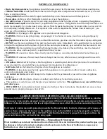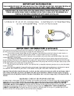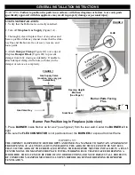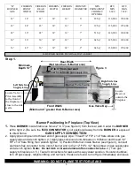
LIGHTING AND OPERATION OF SAFETY PILOT KITS AND PILOT ASSEMBLY
IMPORTANT! CHIMNEY DAMPER MUST BE WIDE OPEN! THE FLUE MUST VENT ALL PRODUCTS OF
COMBUSTION. DAMPER AND GLASS DOORS MUST BE FULLY OPEN BEFORE LIGHTING OR
BURNING FOR PROPER VENTILATION AND TO PREVENT HEAT DAMAGE TO THE VAVLE.
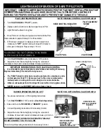
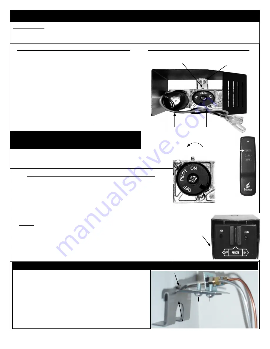
BURNER OPERATION FOR VARIABLE FLAME HEIGHT
SAFETY VARIABLE CONTROL VALVE SKP-N/P-V
VALVE KNOB
PILOT ADJUMENT
SCREW
KNOB CONTROL INDICATOR
WARNING! DO NOT OPERATE BURNER
WITH VALVE HEAT SHIELD.
DC VALVE MOTOR DRIVE
1. Turn
VALVE KNOB
counter clockwise to “ON” position
2. Adjust the burner flame height by turning the valve knob
clockwise to lower and counter-clockwise to raise up to full on.
FULL ON
IMPORTANT INFORMATION ON YOUR VALVE GAS CONTROL
It is intended to prevent premature valve failure and voiding of warranty.
Replace immediately if removed for any reason.
The “EASY Safety Control Valve must be protected to a maximum
ambient temperature of 225° F. Excessive heat to the valve is indicated by
melted plastic or wiring on the valve body and is not warrantable.
Allow an adequate period of cooling after use before closing glass doors.
NEVER operate your BURNER with glass doors closed.
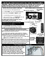
LOWER OR
PILOT POSITION
RECEIVER SLIDE
SWITCH IN “REMOTE”
POSITION
THE RECEIVER
HAS 3 POSITIONS;
“OFF”, “FULL ON”
AND “REMOTE
ACCESS ON”
Note:Consult Operating Instructions for Accessory Control.
KNOB OPERATION
8.
1. See above instructions on Pilot Lighting Instructions
2. Turn
VALVE KNOB
to “ON” position.
(See Knob Operation)
3. Slide switch on the
RECEIVER
to
“REMOTE”
position.
4. Consult Operating Instructions for Accessory Control.
5. Depress the “ON/HI” button on the
TRANSMITTIER
until a click
Is heard. The burner will then light to
“FULL ON.”
DC POWER FROM THE RECEIVER OPERATES THIS UNIT.
DO NOT CONNECT TO A 115V AC LINE.
NOTE:
Reducing the burner flame can be achieved by pressing the “LO” button one
beep at a time to the desired flame height. (Pressing the “ON/HI” button one beep at
a time will raise the burner flame). To verify the burner is completely off, press the
“OFF” button once. During the heating season leave valve knob in “PILOT” position
for convenience. Otherwise, turn to “OFF” position for any prolonged non-use.
Variable flame height can only be achieved via the hand held remote.
PILOT THERMOCOUPLE ASSEMBLY
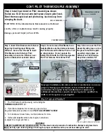
Step 1; Began by attaching Pilot Assembly on Bracket.
Position Pilot bracket as shown. Insert the 10-32 bolts
through the pre-drilled holes of the Pilot Support
Bracket and into the threaded holes of the Pilot
assembly. Tighten with flathead screwdriver, Bend
pilot leads 1/4” after pilot fittings. Bending Pilot leads
at the brass fittings will damage the pilot assembly.
Pilot Support Bracket
Pilot Hood
Bolts
Pilot Leads


