background image

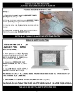
WARNING: If the information in this manual is not followed 
  
exactly, a fire or explosion may result  causing property 
  
damage, personal  injury or loss of life.


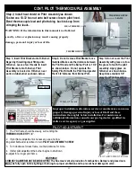
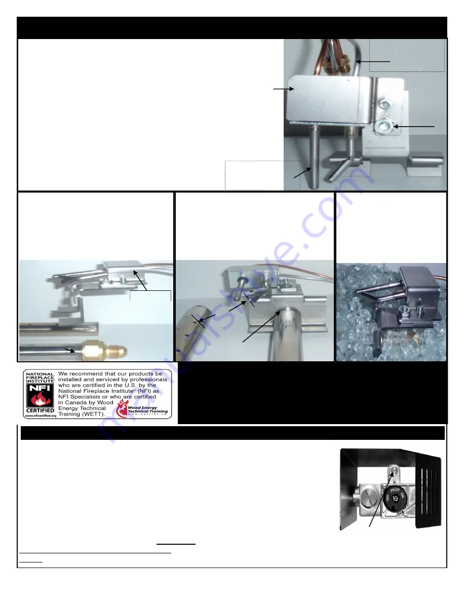
CONT. PILOT THERMOCOUPLE ASSEMBLY 

11. 

PILOT ADJUSTMENT 

Step 2; Install heat shield on Pilot  Assembly as shown    
Fasten one 10-32 hex nut unto bolt screw close to pilot hood.  

Bend thermocouple lead and pilot tubing  back to keep from  

crimping the leads. 

 
THERMOCOUPLE 

Improper installation, alteration, service or maintenance can cause 
property damage, personal injury or loss of life. Read these  
instructions thoroughly before installation. For assistance or  
additional information, consult your gas log dealer, qualified in-
staller, service agency or gas supplier.


HEAT SHIELD 

10
-
32 
H
E

N
U

 
THERMOCOUPLE 

LEADS 

1.  The Pilot flame should be steady, surrounding the  

THERMOCOUPLE TIP 1/4’’ 


2.  If pilot flame adjustment is necessary, use a narrow  

long stem flathead screwdriver to turn 

PILOT ADJUSTMENT SCREW


3.  Turn clockwise for less flame, counterclockwise for more. 


4.  If after pilot adjustment the burner begins to shutdown,  

re-adjust for a longer pilot flame.  

WARNING! 

CHIMNEY DAMPER MUST BE WIDE OPEN! The flue must vent all products of combustion. Damper and glass doors 

MUST be fully open before lighting or burning for proper ventilation and to prevent heat damage to valve. 

PILOT ADJUSTMENT SCREW 

Step 3; Insert Pilot Bracket unto H-Burner.  

Began by threading input fitting unto  
H-Burner. Leave a few threads to insert  
Pilot Bracket unto H-Burner. Pilot  
Assembly is located on H Burner  near 

ports on tubeburner as shown below.  

Step 4; Do not remove Pilot Bracket once  

installed. Make sure the distance between  
the Pilot Hood and the Burner Port is 1 3/4”  
as shown below.  Do not  operate the  
Safety Pilot Kit with the Pilot Hood greater 

then1 3/4”distance from Burner Port.   

Step 5; Do not cover the Pilot 

Assembly with glass or allow 
the glass to touch the pilot 
assembly. Apply glass on  
H-Burner as shown below. 

Keep Glass medium 1/8” 
away from Pilot Assembly. 

H-burner Threads  

Heat Shield 

1 3/4” 

H-burner Threads  

Summary of Contents for SS-H-12

Page 1: ...flammable vapors and liquids in the vicinity of this or any other appliance WHAT TO DO IF YOU SMELL GAS Do not try to light any appliance Do not touch any electrical switch do not use any phone in yo...

Page 2: ...insert or any other accessory not approved for use with this heater A fireplace screen must be in place when the appliance is operating and unless other provisions for combustion air are provided the...

Page 3: ...an to inspect the appliance and to replace any part of the control system and any gas control which has been under water Important Use with other manufacture parts controls remotes parts and accessori...

Page 4: ...r Clamp Damper Blade Opening Height Minimum See Page 5 FIGURE 1 Gas Supply Valve Location may vary per installation Gas Valve Key Burner Pan Positioning In Fireplace side view 1 Place BURNER inside fi...

Page 5: ...ections for leaks with soapy water solution If solution bubbles turn off gas supply retighten fitting and recheck If leaks are found turn off gas immediately and leave 5 Rear Width Not less than H Bur...

Page 6: ...ING DO NOT FLAME TEST FOR LEAKS MANUAL MATCH LIGHTING Standard Match Lit H BURNER FOR NATU RAL GAS ONLY 1 Place lighted match See Figure 4 on glass near inlet end of burner DO NOT HOLD MATCH IN HAND M...

Page 7: ...clockwise to raise up to full on FULL ON IMPORTANT INFORMATION ON YOUR VALVE GAS CONTROL It is intended to prevent premature valve failure and voiding of warranty Replace immediately if removed for an...

Page 8: ...RECEIVER HAS 3 POSITIONS OFF FULL ON AND REMOTE ACCESS ON Note Consult Operating Instructions for Accessory Control KNOB OPERATION 8 1 See above instructions on Pilot Lighting Instructions 2 Turn VAL...

Page 9: ...n PILOT ADJUSTMENT SCREW 3 Turn clockwise for less flame counterclockwise for more 4 If after pilot adjustment the burner begins to shutdown re adjust for a longer pilot flame WARNING CHIMNEY DAMPER M...

Page 10: ...red to act as a heat deflector in protecting combustible fireplace surrounds facing and or mantel if certain minimum clearance cannot be met Be certain that combustible flooring material i e carpet ti...

Reviews: