background image

Step 3

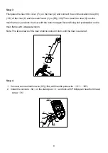
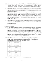
First place the riser trim cover (71) on the riser (2) and connect the communication lines (96)

(101) of the riser (2) and the main frame (1) to (95) (102).Then insert the riser (2) into the

main frame (1) and lock the riser with the inner hexagon flat end fixing bolt preinstalled on the

main frame with l-shaped wrench.

Note: The two screws of the riser shall be locked in turn until the riser is secured.

Step 4

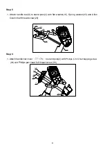
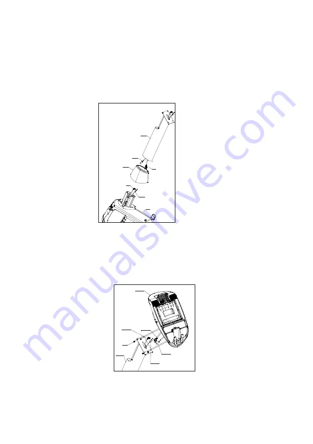
1. Connect communication wire (95) (104) with handle pulse wire

101

105

2. Install the console

62

on the stand post

2

and lock with Phillips pan head full thread

screw

36

.

36

2

105

104

101

95

62

95

96

101

102

2

1

71

8

Summary of Contents for R11-V2

Page 1: ...Thank you Owner s Manual Retain this owner s manual for future reference Read and follow all instructions in this owner s manual Version A 1...

Page 2: ...in the room where this exercise bike is kept Inspect and tighten all parts regularly Replace defective components immediately and or keep the equipment out of use until repair The safety level of the...

Page 3: ...betes or be caused by diabetes feeling obstacle 10 Have skin broken 11 Sicken caused hyperpyrexia 38 over 38 12 Back bone exceptional or back bone bend 13 Pregnant or Menstrual period 14 Feel body exc...

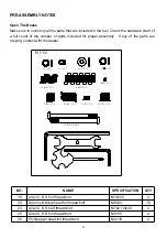
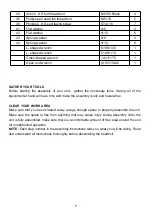
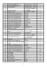
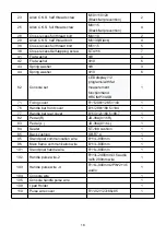
Page 4: ...missing contact with the dealer NO NAME SPECIFICATION QTY 19 Allen C K S full thread bolt M10 20 4 20 Allen cylindrical head full thread bolt M8x20 10 23 Allen C K S half thread bolt M10x110x20 2 25 A...

Page 5: ...bled make sure there is a comfortable amount of free area around the unit for unobstructed operation NOTE Each step number in the assembly instructions tells you what you will be doing Read and unders...

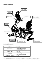
Page 6: ...WITHOUT PRIOR NOTICE TYPE R11 V2 DIMENSION 1615 730 1565mm 63 58 28 74 61 61inch Speed ratio 308 30 Flywheel 245 15kg 9 65inch 33 07lbs Resistance fragment 0 20 Console Handle bar Stand post Back cush...

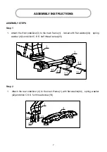
Page 7: ...locked with flat washer 44 spring washer 42 and Allen C K S half thread screw 23 Step 2 1 Attach the rear stabilizer 4 to the main frame 1 with flat washer 44 spring washer 42 and Allen C K S full th...

Page 8: ...riser with the inner hexagon flat end fixing bolt preinstalled on the main frame with l shaped wrench Note The two screws of the riser shall be locked in turn until the riser is secured Step 4 1 Conn...

Page 9: ...ith flat washer 41 Spring washer 43 and Allen Column half thread screw 20 Step 6 1 Attach handle bar cover 77 76 to stand post 2 with Phillips C K S Self tapping screw 38 and Phillips pan head full th...

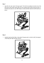
Page 10: ...xing group 6 then install the seat cushion fixing group 6 on the slide seat group 5 Lock with hexagon socket cylindrical head full tooth bolt 20 as shown Step 8 1 Install the seat cushion 84 on the cu...

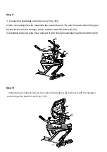
Page 11: ...ng set 6 and lock it with the hexagon socket cylinder head full tooth bolt 20 3 Assemble the pulse tube cover and lock it with cross grooved disc head full tooth bolt 28 Step 10 Install the back cushi...

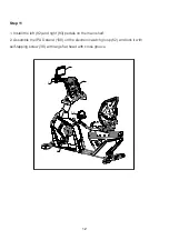
Page 12: ...tall the left 82 and right 83 pedals on the main shelf 2 Assemble the IPAD stand 109 on the electronic watch group 62 and lock it with self tapping screw 38 with large flat head with cross groove 12 8...

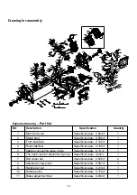
Page 13: ...ustment bar Superficial area 0 034 1 23 44 42 23 44 42 38 38 51 86 38 38 51 86 37 93 20 43 41 38 38 36 39 39 20 41 22 22 34 34 34 34 19 44 42 38 38 51 86 38 38 51 86 56 28 41 40 18 36 30 25 26 87 25 2...

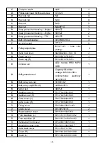
Page 14: ...d screw M6 15 6 26 Allen C K S hollow screw 8 33 M6 15 2 27 Magnetic fixed seat B11 1 28 Cross grooved disc head full tooth bolt M4 10 black 2 29 Allen C K S half thread screw M6 30 black 4 30 Allen C...

Page 15: ...B 1 63 Self generator set Capacity 50 400w voltage 690r min 85v Unidirectional electricity generation 1 64 Belt pulley Axis set 108 192 1 65 Belt pulley set 8500 49 308 9 22 2 1 66 Motor belt 480PJ8 1...

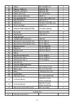
Page 16: ...1 96 Main frame communication wire B11 L 800mm 1 97 Magnetic sensor B11 L 800 2PIN 1 98 Brake wire XH 2P L 600mm 1 99 Magnetic wire XH 3P L 600mm 1 100 Battery 1 101 Stand post handle wire R11 L 800m...

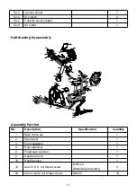
Page 17: ...me set 1 2 Stand post 1 3 Front stabilizer 1 4 Rear stabilizer 1 6 Fixed seat cushion 1 9 Handle bar set 1 10 Handle pulse 1 19 Allen C K S full thread screw M10 20 Black fall prevention 4 20 Allen co...

Page 18: ...rement function hand HRC MP3 USB 1 71 Fixing cover R11 208 128 5 143 1 76 Handle bar front cover B11 289 168 5 144 1 77 Handle bar rear cover B11 312 168 5 88 7 1 82 Pedal R JD 36A 9 16 R 1 83 Pedal L...

Page 19: ...tting on the seat cushion group hold handle bar sets with hands start to do exercise after stepping on the pedals 2 Adjust the foot pad when the bikes is not stable adjust the feet pads Adjust the foo...

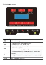
Page 20: ...3 Press to return to the previous when setting data MODE 1 Press to set up or adjust data 2 Press to switch training data display in training mode RESISTANCE 1 For resistance adjustment press for lon...

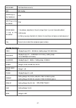
Page 21: ...d press again to close Display function TIME Display Range 0 00 99 99mins Setting range 0 00 99 00mins DISTANCE Display Range 0 0 99 99KM 0 62 13miles Setting range 0 0 99 99KM 0 62 13miles CALORIES D...

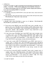
Page 22: ...rt training console will record training data 3 2 If user want to select PROGRAM mode press RESET button return to standby mode In standby mode press PROGRAM entering PROGRAM MODE RPM window display P...

Page 23: ...E window counting down DM window display percentage of body fat in 10 seconds Press BODY FAT turning back to previous mode before BODY FAT with 2 beep sounds 3 6 RECOVERY MODE 3 6 1 In ANY MODE press...

Page 24: ...ess can be eliminated 5 Relax Do 5 minutes of exercise after each exercise especially the stretching and relaxation of the muscles of the foot to avoid long term muscle condensation maintain a muscle...

Page 25: ...ep it for 10 15 seconds then relax Repeat 3 times for each leg As picture 3 shown 4 Quadriceps stretching Grasp the balance with your left hand or the table then extend your right hand backwards and g...

Reviews: