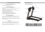
Technical Parameters:
Working voltage
Max load
Outsize
Running area
Motor power
Speed
Incline
Control method
Weight
AC 110V 60Hz
100Kg
L1319*W666*H1133MM
400*1100 mm
1.0 HP
1.0-14.0km/h
0-15%
Console
45kg
M8*16 Screw
M8*45 Screw
M8*10 Screw
Φ8.5 Flat washer
Φ9 Curved spacer
M6*12 Screw
ST4.2*16 Bolts
5mm Hex wrench
6mm Hex wrench
Open-ended wrench
Handlebar
Moving trundle
Left tail housing, right tail housing
Safety lock
Methyl silicon oil
Manual, Qualification
Spare parts list:
1
2
3
4
5
6
7
8
9
10
11
12
13
14
15
16
NO.
Name
Qty.
Remark
3. Installation Procedure
1) First, open the package, take the main body out of the box, and lay it flat on the carpet or
cushions. And the tail of the treadmill should be slightly padded with packaging material.
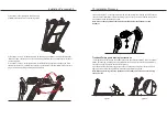
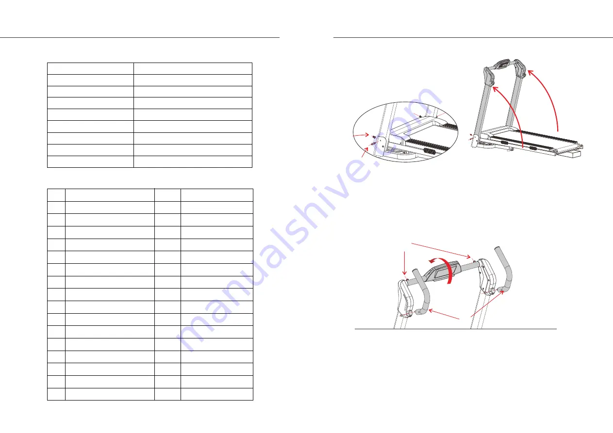
2) As shown in step
①
of the figure, raise the left riser and right riser up to the limit position. As
shown in step
②
of the figure, pass an “M8*45 Screw” through the
Φ8.5 Flat washer to lock the
riser by using a "5MM Hex wrench". As shown in step
③
of the figure, pass an “M8*16 Screw”
through the
Φ9 Spacer to lock the riser by using a "5MM Hex wrench".
(
The riser installation on
the other side is the same as in step
②
and step
③
above).
08 Installation Procedure
Product Introductions 07
Fixed to the back of risers
Fixed to the sides of risers
Fix left and right handlebars
Fix tail housings
Other
Adjust belt
2
2
4
2
2
4
2
1
1
1
2
2
1 for each
1
2
1
②
③
①
④
⑤
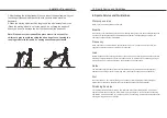
3) As shown in step
④
of the figure above, use a "5MM Hex wrench" to rotate two “M8*10 Screws”
counterclockwise 1-2 times and adjust the angle of the console to the proper position according to
the arrow as shown above. Lock the console clockwise with the “M8*10 Screw” by using a "5MM
Hex wrench".
Insert the left and right handlebars into the left and right risers respectively and fix them with four
“M8*10 Screws” as shown in step
⑤
above. (Note: The handlebars should be parallel to risers).


