Final Installation & Adjustment
Before Connecting Main Airline from Compressor to Control Box.
Clear main airline from compressor from contamination and debris by slowly opening up valve at
compressor and purging line.
If new installation, the main airline may have slag or other
contaminant’s which could cause damage to the valve and other internal components.
Before
hooking up the main airline to the shut-off valve.
Turn off the
shut-off valve by turning the valve
lever to 90
0
to the valve or Off.
Caution:
If the Shut-off valve is in the open position,
the door will start upward when you
apply air pressure to the operator system
.
Step 1
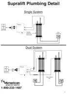
:HUHFRPPHQGUXQQLQJKDUGSLSHDLUOLQHVRXWWR\RXUFRQWUROER[DVVKRZQLQWKHGUDZLQJRQ
SDJH;;RU\RXFDQ
Install 3/8”
polyflow airline from your air compressor to the push-in fitting on the
shut-off valve
Other line sizes may be used.
Step 2
Back off the filter regulator by pulling up on the adjustment knob on top of regulator and turn counter
clockwise until it stops.
Open shut-off valve (inline with valve) Turn the regulator
adjustment knob
FORFNZLVH
slowly until it reaches approximately 60-PSI (Recommended air
pressure
between 45-PSI and 70 PSI).
Step 3
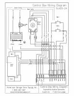
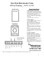
Plug in 110 volt power cord located on the bottom of the control box into receptacle or hardwire.
This should be connected to a grounded receptacle only!!!
Step 4
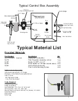
Adjust flow controls by starting with flow controls completely closed (Clockwise) with the locknut
loose.
Open each flow control valve approximately 5 complete turns (Counterclockwise).
Cycle the
door by pushing the open and close buttons located on the control box.
While cycling the door open
and closed continue to turn the flow control valves until the door opens and closes smoothly at the
top and bottom of each cycle.
It is recommended to keep both flow controls set equally.
For additional tuning, adjust flow controls and air pressure at the regulator until door operates to
your desired speed and smoothness.
Note
:
Each flow control valve will control the speed of it’s direction.
Tighten lock nut located on flow
control when adjusted completely.
For complete explanation of how the flow control works, see next page.
Step 5
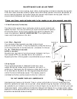
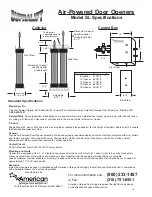
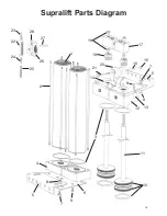
Inspect entire operator cylinder assembly, chain, sprocket assembly and piston rods for proper align-
ment, adjust as needed.
12


