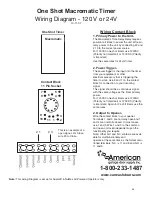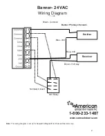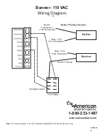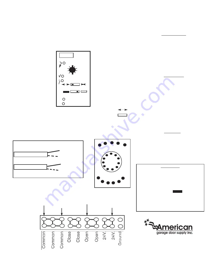
Telco
Telco
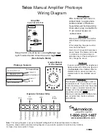
Manual Amplifier Photoeye
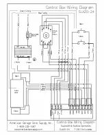
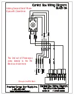
Wiring Diagram
10
1
LT
LR
8 7 6 5 4
10 11 1 2 3
9
Range
Light Function
Range Switch should be set on
Long Range
Light Function Switch Should be set on
Light
(Non-Failsafe Mode)
Note:
This wiring Diagram is set up for Supralift & Magnelift Air-Powered Operators. For Electric
Operators, please refer to electrical wiring diagram of your electric operator for terminal strip locations
for Open, Common and 24 V. Power.
# 3
# 1
Operation
Adjust gain adjustment on amplifier
dial clockwise until green light turns
on.
When adjusting, the eyes must be
more that 5 feet apart.
Red LR or LT failure LED indicates a
sensor failure. The failure can be due
to a broken or shorted wiring or a
defective sensor. Check wiring and if
O.K, change the sensor.
1-800-233-1487
www.carwashdoors.com
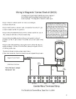
Wiring Eyes
Wire numbered terminals on
contact block to appropriate
numbers listed on Receiver,
Transmitter and Terminal Strip.
Once wired, plug in amplifier to
11 pin socket located on
contact block.
Contact Block
11 Pin Socket
Operator Terminal Strip
Non-Shielded- # 8
Yellow- # 6
Black- # 7
Red- # 5
Photoeye Sensors
Emitter/Transmitter- LT
Receiver- LR
To Contact Block
Splicing
If sensor cables need to be lengthened.
Splice cables with similar wire type and
size.
Example-
Use shielded cable for
shielded wire on sensor and use non-
shielded wire for non-shielded sensor
wire.
# 2
Supply
# 10
Supply
Attention!!!
This diagram shows photoeyes wired in
non-failsafe mode. If you choose to wire
in fail safe mode, wire #4 from the contact
block to open on operator terminal strip
instead of #3. The light function switch
should be set to dark.
Warning: In failsafe mode, if either photo-
eye or system fails, the door will open
automatically.
Gain
Amplifier
Part # PA11-B302T-05
P/N-LR110LTB3815-05
P/N-LT110LYB3815-05
000024
0024
24

