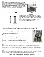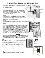
Step 9
Adjust operator
horizontal
alignment with shaft sprocket and
door/track by adjusting the top and bottom track brackets.
The
brackets can be adjusted by loosening the bolts that connect the
top and bottom operator track brackets and the operator top
plates.
The opener can be adjusted in two directions for proper
alignment.
Tighten the bolts securely when complete.
Important:
The centerline of the operator should be plumb with the
center of the sprocket teeth on the torsion shaft of the door.
The operator should also be plumb 90
0
to the torsion shaft
as well.
If the operator is not plumb, the piston rods will cause
friction and
premature failure of rod seals.
Step 11
Finish tightening the chain by turning the turnbuckle clockwise until the chain is snug.
Tighten
the locknut on one of the turnbuckle studs to prevent the chain from loosening
during
use.
Step 12
Pull the chain assembly up until the turnbuckle is approximately 1"
below the sprocket on the torsion shaft. The turnbuckle should be on
the front side of the sprocket. (Figure 6)
Step 14
Push the piston rod on the cylinder closest to the wall (close cylinder) all the way down until the
piston bottoms out in the cylinder, then raise the piston rod 1"-1-1/2”
upward and tighten the set
screw on the aluminum collar to lock the chain.
Tip:
Rotate the piston rod to one side to tighten the
set screw then rotate back to proper position.
Tighten locknuts on top and bottom of aluminum collar.
Step 15
Raise door to your desired opening height, push the piston rod on the cylinder furthest from the wall
(open cylinder) all the way down, and tighten the set screw on the aluminum collar.
Dual Operator systems should be installed identically.
Adjustment
Bolts
C
90
0
To Level Shaftline
Plumb with
Sprocket
Figure 4
Figure 5
Track Bracket
C
Front View
Side View
Step 13
Insert the ¼" key into the sprocket and tighten the set screw securely
on the shaft sprocket.
For final setting of the sprocket, it is recommend-
ed to keep the sprocket as close to the bearing plate as possible to
prevent deflection of the shaft.
If it is necessary to have the sprocket
more than 4”
from the bearing plate and track assembly, use a
additional bearing plate to stabilize the end of the torsion shaft.
The sprocket must always be plumb with the operator to prevent premature
seal wear.
Figure 6
8


