Page 23
200 Series 36V
15312
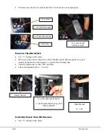
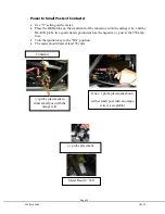
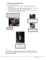
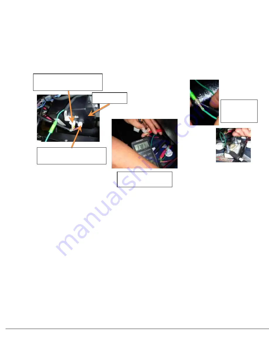
Place one probe on one of the three purple wires and one probe to a good chassis
ground.
Turn the ignition key to the “ON” position. The meter should read in excess of 36
volts.
Repeat for the other purple wires. All purple wires are tied together. If one is not
getting power and the others are, a bad crimp or broken wire may be the problem.
Action
If the proper voltage is not present, check all connections and splices in the 36 volt harness
and repair as necessary. Wiring must be traced to locate the item that is disrupting the
circuit.
Relay
Make sure it makes a faint “click” when the key is powered ON and again when key
is OFF.
If the “click” is not present, check the wiring to the relay. With the Key ON, verify
12V exists between at the black connection.
If 12V exists and Relay does not click, replace the relay.
(+) probe placement
and meter result
4-Pin Connector with 2
power feeds (purple wires)
Controller
10-Pin Connector with 1
power feed (purple wire)
(-) probe
placement
options
Summary of Contents for 36V 200 Series
Page 1: ...15312 Service Manual 200 Series 36V...
Page 12: ...Page 9 200 Series 36V 15312 Section 6 ELECTRICAL SYSTEM SCHEMATICS Figure 1 Vehicle Schematic...
Page 13: ...15312 200 Series 36V Figure 2 Motor Controller Schematic...
Page 18: ...Page 15 200 Series 36V 15312 Section 8 BRAKES BRAKE SYSTEM REPLACEMENT...


