15312
200 Series 36V
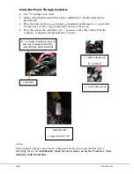
Controller Power Through Contactor
Use “V” setting on the meter.
Make certain that the resistor has been re-installed if it was disconnected in a
previous test.
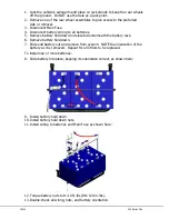
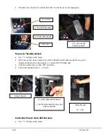
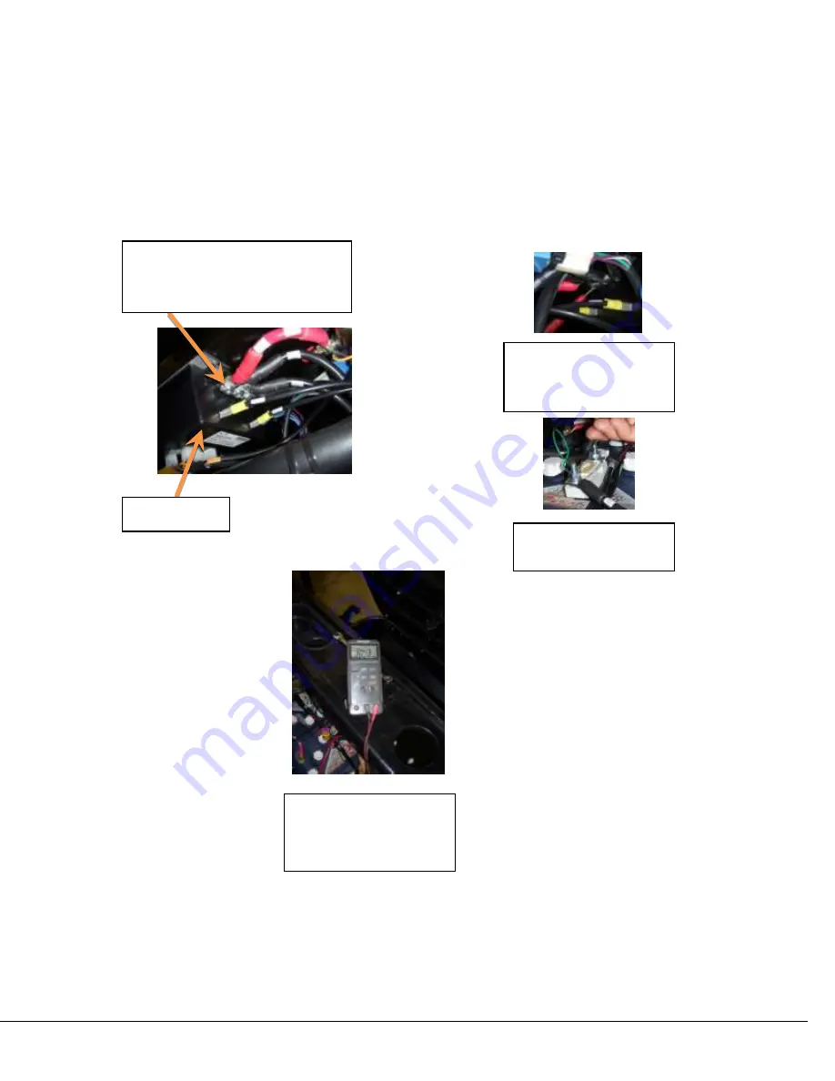
Place the black probe to a good chassis ground such as the negative (-) post at the
350 amp fuse or where the ground cable attaches to the frame.
Place the other at the controller’s “B +” position on the cable coming from the
contactor. It should read approximately 30 volts.
Action
If the required voltage is not present, wiring must be traced to locate the item that is
disrupting the circuit.
Additionally, check for a hot resistor across the Contactor. This
indicates a failed controller.
Meter Result
Approximately 30V
Controller
B + terminal (Farthest rearward
and only terminal with both a
red and black cable attached)
(-) probe placement
Main Fuse
(+) probe placement
B+ Terminal
Summary of Contents for 36V 200 Series
Page 1: ...15312 Service Manual 200 Series 36V...
Page 12: ...Page 9 200 Series 36V 15312 Section 6 ELECTRICAL SYSTEM SCHEMATICS Figure 1 Vehicle Schematic...
Page 13: ...15312 200 Series 36V Figure 2 Motor Controller Schematic...
Page 18: ...Page 15 200 Series 36V 15312 Section 8 BRAKES BRAKE SYSTEM REPLACEMENT...

