32 - FORM NO. 56041704
American-Lincoln
6150
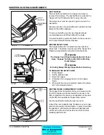
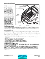
HOPPER
The hopper houses the debris
compartment, the dust control
fi lter and the removable
dust baffl e. For maximum
performance and service life,
keep the hopper clean and
inspect the seals and fl aps
daily. Clean the hopper prior
to parking the sweeper at the
end of the day. A clean hopper
will make inspecting the fl aps
and seals much easier and will
prevent premature deterioration
of hopper components. Do not
leave the hopper full of debris
while in storage or when parked
for extended periods of time
TO CLEAN HOPPER
Once the hopper has been
emptied the insides of the
hopper should be rinsed out
with water.
TO CHECK HOPPER SEALS
The Hopper seals are important to positive dust control while sweeping. Damaged seals will reduce vacuum
pressure at the broom. Inspect for cuts, tears and proper positioning of the seal material. Replace all seals
that become damaged.
DUST CONTROL FILTER
The dust control fi lter should be checked daily for damage and cleaned if necessary. A damaged fi lter must
be replaced to prevent damage to other dust control system components. Inspect the fi lter for tears in the
fi lter media or excessive dirt lodged in the pleats. A tear in the fi lter media will allow dirt to pass through the
fi lter and can be easily seen as a dirty patch on the top side on the fi lter. Cleaning the fi lter is necessary when
the fi lter shaker fails to adequately clean the pleats.
TO CHECK THE DUST CONTROL FILTER
1. Park the sweeper on a smooth level surface. Turn the key switch to the “O” position and engage the
parking brake.
2. Raise the hopper lid for access to the fi lter compartment.
3. Turn the latch, lift the fi lter frame and remove the fi lter.
4. Inspect the panel fi lter for tears and clean or replace if necessary.
5. Reinstall
the
fi lter, lower the fi lter frame and engage the fi lter latch.
6. Close the hopper cover.
TO CLEAN THE DUST CONTROL FILTER
Clean the dust control fi lter when the shaker fails to adequately clear the fi lter. The fi lter can be cleaned with
compressed air not to exceed 100psi.
To clean the fi lter with compressed air, apply the compressed air to the top of the panel to backfl ush the
lodged dirt from the fi lter pleats. Be careful to not damage the fi lter media while cleaning. The fi lter can
be cleaned with a solution of soap and water. If this cleaning method is used do not use the fi lter until it is
completely dried.
SERVICE INSTRUCTIONS
C0739
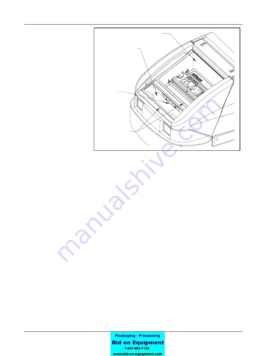
FIGURE 33
FILTER
COMPARTMENT
DUST
BAFFLE
HOPPER
SEALS
DEBRIS
COMPARTMENT
C-0739
Summary of Contents for 6150
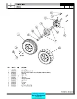
Page 39: ...FORM NO 56042480 6150 IC 4 06 5 REAR WHEEL 07 10 ...
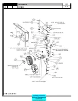
Page 41: ...FORM NO 56042480 6150 IC 6 06 5 VAC FAN 07 10 ...
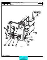
Page 45: ...FORM NO 56042480 6150 IC 10 06 5 FLAP ASSEMBLY WHEEL WELL 07 3 C 1227 ...
Page 51: ...FORM NO 56042480 6150 IC 16 06 5 C1250 H46 H43 H39 H47 H53 SIDE BROOM ASSEMBLY 07 3 ...
Page 53: ...FORM NO 56042480 6150 IC 18 06 5 SIDE BROOM LIFT SYSTEM 07 10 ...
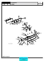
Page 57: ...FORM NO 56042480 6150 IC 22 06 5 BROOM CHAMBER FLAPS SEALS 07 10 ...
Page 59: ...FORM NO 56042480 6150 IC 24 06 5 BRAKE PEDAL 80805 1 6 05 07 3 ...
Page 63: ...FORM NO 56042480 6150 IC 28 06 5 SEAT FLOOR ASSEMBLY 07 10 ...
Page 71: ...FORM NO 56042480 6150 IC 36 06 5 CONTROL RELIEF VALVE 3 CYL KUBOTA GAS DIESEL 07 3 ...
Page 73: ...FORM NO 56042480 6150 IC 38 06 5 FWD REV CONTROL 2 CYL KAWASAKI GAS 07 10 ...
Page 75: ...FORM NO 56042480 6150 IC 40 06 5 FW REV CONTROL 3 CYL KUBOTA GAS DIESEL 07 3 ...
Page 81: ...FORM NO 56042480 6150 IC 46 06 5 FUEL TANK GAS 07 10 ...
Page 83: ...FORM NO 56042480 6150 IC 48 06 5 FUEL TANK DIESEL 07 10 ...
Page 87: ...FORM NO 56042480 6150 IC 52 06 5 80806 2 2 05 HOPPER COVERS GASKET ASSEMBLY ...
Page 91: ...FORM NO 56042480 6150 IC 56 06 5 H26 H80 H86 H26 H98 H22 C 1207 9701 DUMP DOOR ...
Page 97: ...FORM NO 56042480 6150 IC 62 06 5 HYDRAULIC PUMP 3 CYL KUBOTA GAS DIESEL 07 3 80851 SHT01 ...
Page 99: ...FORM NO 56042480 6150 IC 64 06 5 ENGINE COVER 30 25 32 31 80813 0 3 07 ...
Page 101: ...FORM NO 56042480 6150 IC 66 06 5 80841 8 05 ACCESS COVER ASSEMBLY ...
Page 105: ...FORM NO 56042480 6150 IC 70 06 5 ENGINE 3 CYL KUBOTA GAS 07 10 ...
Page 107: ...FORM NO 56042480 6150 IC 72 06 5 ENGINE 3 CYL KUBOTA DIESEL 07 10 ...
Page 109: ...FORM NO 56042480 6150 IC 74 06 5 ENGINE 3 CYL DUAL FUEL LP 07 10 ...
Page 113: ...FORM NO 56042480 6150 IC 78 06 5 80839revF 8 05 HYDRAULIC HOSE DIAGRAM 2 CYL ...
Page 125: ...FORM NO 56042480 6150 IC 90 06 5 DECALS 08 7 ...
Page 127: ...FORM NO 56042480 6150 IC 92 06 5 DECALS continued 07 10 ...
Page 129: ...FORM NO 56042480 6150 IC 94 06 5 C1335 7 04 2 CYLINDER LP CE MODELS ONLY ...
Page 136: ...101 FORM NO 56042480 6150 IC 06 5 HYDRAULIC SCHEMATIC 2 CYL GAS LP DIESEL 08 7 ...
Page 138: ...103 FORM NO 56042480 6150 IC 06 5 HYDRAULIC SCHEMATIC 3 CYL KUBOTA GAS DIESEL ...

