background image

American-Lincoln 

FORM NO. 56041704 - 35

6150

BATTERY SERVICE INSTRUCTIONS
BATTERY CHARGING INSTRUCTIONS - cont.

Check the liquid level in the battery at least once a week and add water when low.  Use only distilled water.  
Fill the batteries after charging the batteries to prevent electrolyte from spilling over on the tops of the 
batteries during the charging process.

 WARNING

The use of an extension cord with the charger should be avoided.  Risk of fi re and electrical shock 

is possible if the wrong type or size extension cord is used.  If an extension cord must be used, only 

use a three conductor number 12 AWG cord with ground, properly wired, in good electrical condition 
and keep it as short as possible.  Locate all cords so that they cannot be stepped on, tripped over, or 

otherwise subjected to damage or stress.

 WARNING

Verify that the AC power source to which the charger is to be connected is capable of supplying the 

current specifi ed on the charger nameplate.

 WARNING

Keep all charger ventilation holes at least 2 inches away from walls or other objects.  Do not allow 

vent holes to become obstructed.

 WARNING

Do not operate charger that has been damaged or shows physical signs of damage.  Have charger 

serviced by a qualifi ed professional repair person.

 WARNING

Disconnecting the battery connector with the key switch in the “I” position will cause sparks that 

could ignite explosive hydrogen gas generated by the batteries.  To prevent serious injury or possible 

property damage, Turn key switch to “O” position before disconnecting battery cable from machine 

for charging or service.

 WARNING

Lead acid batteries generate gases which can cause an explosion.  Keep sparks and fl ames away 

from batteries.  NO SMOKING.  Charge batteries only in area with good ventilation and always leave 
the seat compartment cover open while charging batteries.  Do not disconnect the charger from the 

batteries before disconnecting the AC power cord.  Disconnecting the battery cable with the charger 

plugged in could cause an explosion.

TO CHARGE THE MOTOR POWER BATTERIES (Battery Powered Machines Only)

1.  Read the detailed instructions provided on the charger.
2.  Be sure all controls are “OFF” and machine is located in an area with good ventilation.
3.  Open the seat compartment cover.  The cover must remain open during the charging process.  Use the 

seat compartment latch to hold the cover open.

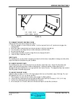
4.  Disconnect the battery from machine power supply cable using the quick disconnect provided.
5.  Connect the charger cable to the battery connector.
6.  Plug the charger into properly grounded AC outlet.  Be sure to verify the operating voltage of your 

charger.


The chargers supplied with machine operate at 115 VAC @ 60 HZ or 230 VAC @ 50 HZ.

7.  The charger will begin charging the batteries after a short period of time.  The charger will shut off 

automatically when the charging process is complete.

8.  Unplug the charger from the grounded AC outlet before disconnecting the charger from the battery.
9.  Disconnect the charger cable from the battery.
10.  Check the electrolyte level in the battery after charging.  Add distilled water if needed.
11.  Reconnect the machine power supply cable to the battery cable.
12.  Lower the seat compartment cover and perform the pre-start checks before operating the machine.

SERVICE INSTRUCTIONS

Summary of Contents for 6150

Page 1: ...tempting any service or maintenance procedure to your machine could result in injury to you or to other personnel damage to the machine or to other property could occur as well You must have training in the operation of this machine before using it All directions given in this book are as seen from the operator s position at the rear of the machine 6150 POWER SWEEPER Form Number 56041704 Revised 3...

Page 2: ...PPER TEMPERATURE LIGHT 13 DUMP DOOR LIGHT 13 SEAT POSITION ADJUSTMENT 14 TURN SIGNALS OPTION 14 BACK UP ALARM 14 BATTERY CONDITION METER 14 FILTER SHAKER SWITCH 15 DUST CONTROL SWITCH 15 BROOM CONTROL LEVER 15 SIDE BROOM LEVER 16 SIDE BROOM ADJUSTMENT 16 MAIN BROOM LEVER 16 MAIN BROOM ADJUSTMENT 16 HOPPER DOOR LEVER 17 HOPPER LIFT LEVER 17 DEBRIS DOOR 17 DUST BAFFLE 18 HOPPER SAFETY ARM 18 HOPPER ...

Page 3: ...NE STORAGE 27 SERVICE CHART 28 SERVICE INSTRUCTIONS 28 MAIN BROOM 30 TO CHECK THE MAIN BROOM SWEEP PATTERN 30 TO ADJUST THE MAIN BROOM HEIGHT 30 TO REPLACE THE MAIN BROOM 30 MAIN BROOM LEVEL ADJUSTMENT 30 SIDE BROOM 31 TO CHECK THE SIDE BROOM SWEEP PATTERN 31 TO ADJUST THE SIDE BROOM HEIGHT 31 TO CHANGE THE SIDE BROOM 31 HOPPER 32 TO CLEAN HOPPER 32 TO CHECK HOPPER SEALS 32 DUST CONTROL FILTER 32 ...

Page 4: ...wered 36 volts HYDRAULIC SYSTEM GAS DIESEL LP POWERED MACHINES The engine furnishes power through a coupling to a fixed displacement hydraulic gear pump The pump provides controlled oil flow to various operator controlled hydraulic valves which supply hydraulic power to the hopper dump system and motors on the rear wheel main broom side broom and vacuum fan Hydraulic system is protected by two fil...

Page 5: ...ust control Filter can be washed HOPPER Constructed of steel hopper provides adequate ground clearance and floating flaps Capacity 10 ft 283 L Weight Capacity 700 lbs 317 5 kg BROOMS CONTROLS A separate lever raises and lowers the main broom which allows it to be set in the restricted down or free float position Side broom raise lower level DUMPING SYSTEM Variable dump empties debris from ground l...

Page 6: ...6 FORM NO 56041704 American Lincoln 6150 MODEL NO SERIAL NO WARNING 54 75 53 00 77 75 197 cm 135 cm 139 cm 60 00 147 cm 223 cm 88 00 87 00 221 cm C 0725 MACHINE DIMENSIONS ...

Page 7: ...s can easily be done by providing an insulated wire Permanently attached to the container with a battery clip attached to the other end 4 Check engine crankcase oil level 5 Check radiator coolant level Permanent type antifreeze is added at the factory to provide protection to approximately 35 F 2 C To retain this level of protection always add 1 2 part water to 1 2 part antifreeze 6 Check fluid le...

Page 8: ...EL FOR THE SAFE OPERATION OF THIS MACHINE READ AND UNDERSTAND ALL WARNINGS CAUTIONS AND NOTES WARNING Machines can ignite flammable materials and vapors Do not use with or near flammables such as gasoline grain dust solvents and thinners WARNING Heavy machinery Improper use can cause personal injury WARNING Operate only when lids doors and access panels are securely closed WARNING Use care when re...

Page 9: ...ects across the battery terminals or the tops of batteries WARNING Maintenance and repairs must be done by authorized personnel only Tighten all fasteners Keep adjustments according to the specifications given in the service manual for the machine Keep the electrical parts of the machine dry For storage keep the machine in a building WARNING Make sure that all labels decals warnings cautions and i...

Page 10: ...r no circumstances should Ether or other starting aids be used in conjunction with the glow plugs To prevent damage to the glow plug switch do not use for more than 60 seconds They key switch must be placed in the ON position before using the glow plug switch CHOKE CONTROL The choke control is located on the left side console and is used to aid in starting the engine The choke governs the mixture ...

Page 11: ...e position is variable from idle to max engine speed and may be adjusted to suit operating conditions The locking feature of the engine throttle control consists of a rubberized push button that unlocks the control for adjustment Push down on the button while positioning the control to the desired setting then release the button to unlock the throttle in place Pull up on the throttle to increase e...

Page 12: ...n the pedal TO GO BACKWARD Put pressure on the lower portion of the pedal Speed increases when additional pressure is placed on the pedal To increase braking action while sweeper is moving forward gently put pressure on the lower portion of the pedal To Increase braking action while traveling in reverse gently put pressure on the upper portion of the pedal To adjust the foot pedal height for opera...

Page 13: ...When this occurs the sweeper charging system is not working properly and must be serviced by a qualified service technician DUST CONTROL LIGHT option The Dust Control Light Illuminates to indicate that the dust control filter is clogged When this occurs stop sweeping and use the filter shaker to clear dirt and debris from the filter After using the filter shaker continue sweeping HOPPER TEMPERATUR...

Page 14: ...ated by a switch in the foot pedal and automatically emits a loud audible noise when the machine is driven in reverse BATTERY CONDITION METER Battery Power Only The battery condition meter is located on the right side of the instrument panel The condition meter indicates the level of charge in the batteries The batteries are sufficiently charges when the needle stays in the green area on the gauge...

Page 15: ... the dust control system To turn on the dust control system for NORMAL Sweeping press on the top portion of the switch To Turn off the dust control system for sweeping in wet conditions press on the lower portion of the switch This will prevent the filter from being damaged by water pickup while sweeping BROOMS CONTROL LEVER The brooms control lever is located on the operator s compartment center ...

Page 16: ...he main broom sweep height Use the brooms lever on the operator s center console to turn on the main broom To lower the main broom grasp the lever and move it to the left out of the UP position and place in the SWEEP or FLOAT position The SWEEP position is used for normal sweeping and should be used under most sweeping conditions The FLOAT position is used for sweeping very uneven surfaces only Us...

Page 17: ...he operation of the hopper lift system The lever is spring loaded to the center position which stops hopper movement and HOLDS the hopper at the present position NOTE To provide hydraulic power to the hopper controls the broom control lever must be in the center Neutral Position To raise the hopper for dumping move the lever back to the RAISE position and hold until the hopper reaches the desired ...

Page 18: ...opper WARNING For Safety Always Empty Hopper Before Servicing TO ENGAGE THE SAFETY ARM 1 Empty hopper 2 Set the parking brake 3 Raise the hopper 4 Lift safety arm to engage the slot on the hopper frame 5 When work has been completed replace the safety arm to the stowed position HOPPER FILTER COMPARTMENT COVER The Hopper Filter Compartment Cover is located on the top of the hopper and opens forward...

Page 19: ...e warning bank The hopper temp sensor is a resetable thermal switch which is located in the hopper filter compartment near the vacuum fan intake When the hopper temp light illuminates carefully investigate for a possible fire in the hopper The sensor will not reset until the temperature in the hopper has dropped below 133ºF To reset the temp sensor press the reset button ENGINE COMPARTMENT LATCH T...

Page 20: ...open the main broom door reach inside the hole in the door and lift up on the latch handle The door latch will automatically engage when the door is closed SEAT COMPARTMENT COVER The seat compartment cover opens to allow easy access to various components which will need to be inspected or serviced periodically The cover opens forward and has a safety latch to hold the cover in the open position WA...

Page 21: ...sy method of disconnecting power to the machine for service or charging of the batteries Plug the charger into the connector to charge the batteries WARNING Disconnecting the battery connector with the key switch in the I position will cause sparks that could ignite explosive hydrogen gas generated by the batteries To prevent serious injury or possible property damage turn key switch to O position...

Page 22: ...NES In actual sweeping there is no single pattern that can be set forth in this manual Each installation has its own conditions and the operator can readily set his own pattern using these guidelines Pick up large debris before sweeping with machine Use the machine to sweep debris from narrow aisles into main aisle After the machine has made a sweeping run push the filter shaker control button for...

Page 23: ...instructions on the LP fuel system and replacement of tanks Use the pre start check list and follow the service chart for daily check points Read and follow the safety precautions to assure safe trouble free operation Gasoline powered machines use regular grade unleaded gasoline Turn the engine off before dispensing fuel into the gasoline powered machine WARNING To prevent possible fire Never fill...

Page 24: ...r to using the machine TO CHARGE BATTERIES Charge the batteries at the end of each day or when the battery condition meter indicates low battery voltage The batteries need to be charged when the needle stays in the red zone while the machine is being operated When charging batteries only use the quick disconnect provided ensure correct polarity Follow the Battery Charging Instructions provided in ...

Page 25: ...on the pedal to obtain the desired speed 6 To stop allow the foot pedal to return to the centered position Pedal will return to neutral when pressure is released WARNING Do Not Turn The Steering Wheel Sharply When The Machine Is In Motion The Sweeper Is Very Responsive To Movement Of The Steering Wheel Do Not Make Sudden Turns WARNING Machines Can Ignite Flammable Materials And Vapors Do Not Use W...

Page 26: ...for wear or damage 3 Check all flaps for wear damage and adjustment 4 Fill the fuel tank 5 Check all systems for leaks 6 Close the LP storage tank valve LP Powered machines only WARNING The Gasoline Tank Fill Cap Is Located Behind The Drivers Seat Do Not Mistake The Hydraulic Reservoir For The Gasoline Tank BATTERY CHARGING INSTRUCTIONS Battery powered Machines Only Charge the batteries at the end...

Page 27: ...equivalent will minimize the formation of fuel gum deposits during storage Such an additive may be added to the gasoline in the fuel tank of the engine The following procedure should be used to prepare the machine for storage 1 All fuel should be removed from the tank Run the engine until it stops from lack of fuel 2 While engine is still warm drain oil from the crankcase Refill with fresh oil 3 R...

Page 28: ...ncoln 6150 SERVICE CHART American Lincoln MODEL NO SERIAL NO WARNING C1251 1 16 1 16 2 17 19 2 17 19 4 21 4 21 11 20 11 20 13 22 13 22 13 5 5 7 23 25 23 25 8 8 9 10 20 32 27 9 10 20 32 27 6 15 3 36 37 38 3 36 37 38 12 14 34 12 14 34 ...

Page 29: ...oom end for end 16 Clean or replace panel filters 17 Perform recommended engine maintenance See engine manual EVERY 100 HOURS 18 Change crankcase oil 19 Change engine oil filter 20 Check fuel hose for leaks or deterioration 21 Check radiator hoses and clamps 22 Lubricate steering yoke pivot bearings 23 Lubricate front wheel bearings 24 Lubricate all moving joints 25 Check brake pads for wear and a...

Page 30: ...the adjustment knob clockwise to DECREASE the sweep pattern width TO REPLACE THE MAIN BROOM The Main Broom should be replaced when the bristles become worn to less than 2 The main broom is held in place by the right side broom door This feature provides for easy removal and installation of the main broom without the need for special tools or equipment Follow the instructions below for main broom r...

Page 31: ...ooms height is necessary by examining the floor contact area the broom should contact the floor as shown in figure 34 above Adjust the side broom height if the contact area on the floor does not match the diagram TO ADJUST THE SIDE BROOM HEIGHT Turn the side broom adjustment knob to change the side broom sweep height Re check for proper sweep pattern after adjustment Turn the adjustment knob count...

Page 32: ...media or excessive dirt lodged in the pleats A tear in the filter media will allow dirt to pass through the filter and can be easily seen as a dirty patch on the top side on the filter Cleaning the filter is necessary when the filter shaker fails to adequately clean the pleats TO CHECK THE DUST CONTROL FILTER 1 Park the sweeper on a smooth level surface Turn the key switch to the O position and en...

Page 33: ...e dust flaps are used on the wheel well broom chamber and broom door Inspect the flaps daily and replace any flap that shows signs of wear or deterioration All flaps should be replaced when worn or damaged to the point that they can no longer perform their normal function The adjustable flaps have slotted mounting holes to facilitate adjustment TO ADJUST THE DUST FLAPS Adjust the flaps so there is...

Page 34: ...lution To clean the terminals and connectors use a terminal and connector cleaning tool ATTENTION Never allow the soda solution to enter the cells This will permanently discharge the battery BATTERY CHARGING INSTRUCTIONS Battery powered Machines Only Charge the batteries at the end of each day or when the battery condition meter indicated low battery voltage The batteries need to be charged when t...

Page 35: ...able from machine for charging or service WARNING Lead acid batteries generate gases which can cause an explosion Keep sparks and flames away from batteries NO SMOKING Charge batteries only in area with good ventilation and always leave the seat compartment cover open while charging batteries Do not disconnect the charger from the batteries before disconnecting the AC power cord Disconnecting the ...

Page 36: ...6 revised 2 09 FORM NO 56042480 PARTS LIST After Serial Number 630950 American Lincoln Models 576 500 576 500CE 576 503 576 503CE 576 504 576 504CE 576 505 576 505CE 576 506 576 506CE 6150 IC Power Sweeper ...

Page 37: ...OPPER LIFT 54 HOPPER SIDES 55 DUMP DOOR 56 SAFETY ARM 58 HYDRAULIC FILTER 2 CYL 59 HYDRAULIC FILTER 3 CYL KUBOTA GAS DIESEL 60 HYDRAULIC PUMP 2 CYL GAS LP 61 HYDRAULIC PUMP 3 CYL KUBOTA GAS DIESEL 62 ENGINE COVER 64 ACCESS COVER 66 ENGINE 2 CYL KAWASAKI GAS 68 ENGINE 3 CYL KUBOTA GAS 70 ENGINE 3 CYL KUBOTA DIESEL 72 ENGINE 3 CYL DUAL FUEL LP 74 HYDRAULIC HOSE DIAGRAM 3 CYL 76 HYDRAULIC HOSE DIAGRA...

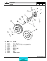
Page 38: ...c Non Marking Zoah model 576 508 only 3 8 11 00030 2 Grease Cap 4 8 33 09089 2 Hub and Drum 5 8 80 05035 10 Stud 6 2 00 04621 4 Bearing Cup 7 2 00 02079 2 Bearing Cone Sealed 8 2 00 04622 2 Bearing Cone 9 2 00 05026 2 Nut 10 2 00 05024 2 Flat Washer 11 2 00 02436 2 Cotter Pin 12 2 00 02312 8 Lock Washer 1 2 HS Med 13 2 00 02689 8 Screw 1 2 20 x 1 000 HHC FRONT WHEEL 08 7 ...

Page 39: ...FORM NO 56042480 6150 IC 4 06 5 REAR WHEEL 07 10 ...

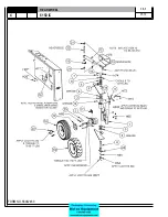
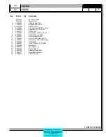
Page 40: ...05017 1 Hydraulic Cylinder 7 70 00021 1 Cylinder Seal Kit service 13 8 66 00149 1 Rod End 14 2 00 00566 1 Grease Zerk 15 2 00 04892 1 Fitting 90 16 2 00 05253 1 Clamp 17 2 00 04974 2 Fitting Straight 18 8 30 05175 2 Guard Hose 19 7 11 00048 1 Cap 7 8 Hex Nut 20 8 55 08128 1 Pin Steering Cylinder Pivot 21 8 15 01032 3 Collar 22 8 33 09093 1 Hub Drive Wheel 23 8 80 05035 5 Stud 24 7 13 07176 1 Clamp...

Page 41: ...FORM NO 56042480 6150 IC 6 06 5 VAC FAN 07 10 ...

Page 42: ...Gr 5 7 2 00 00451 1 Washer Flat 8 2 00 00484 2 Flat Washer 625 X 375 X 046 9 2 00 00632 1 Nut 5 16 18 Insert Fiber 10 2 00 00641 4 Nut Fiber Insert 1 4 20 11 2 00 00644 4 Nut Hex Insert Fiber 5 16 18 12 2 00 02310 2 Washer Lock 3 8 Helical Spring 13 2 00 03454 1 Hose Clamp 14 2 00 05204 2 13 16 16 Orsmx1 2 14 Nptf 90 15 2 95 04689 2 Washer Axle 16 8 23 00012 1 Fan Impeller 17 8 29 00183 1 Gasket B...

Page 43: ...FORM NO 56042480 6150 IC 8 06 5 C1213 1 9702 H20 H20 H80 H23 H27 H27 H27 H15 H26 H26 H26 H27 10 6 7 8 3 4 1 5 9 2 BROOM DOOR ...

Page 44: ... 1 Plate Idler Retainer 7 8 25 08212 2 Flap 8 8 13 07145 2 Clamp 9 8 75 01199 1 Spacer Broom Door Latch 10 8 29 00232 1 Gasket HARDWARE USED H15 2 00 00221 12 Screw 1 4 20 x 750 HHC H20 2 00 00203 6 Screw 1 4 20 x 1 500 HHC H23 2 00 01980 1 Screw 1 4 20 x 1 500 HHC H26 2 00 00641 14 Nut 1 4 20 Insert Fiber H27 2 00 03702 14 Washer 625 x 281 x 063 H80 2 00 02196 8 Carriage Bolt 1 4 20 x 1 000 RHM H...

Page 45: ...FORM NO 56042480 6150 IC 10 06 5 FLAP ASSEMBLY WHEEL WELL 07 3 C 1227 ...

Page 46: ...p Rear 4 8 13 07147 2 Clamp Wheel Well Flap Front 5 8 68 05090 1 Seal Broom Chamber Dump Door 6 2 00 05261 1 Threaded Insert 7 8 68 05088 1 Seal Wheel Well Right 8 8 68 05089 1 Seal Wheel Well Left 9 8 34 09028 1 Insulation Top 10 8 34 09034 1 Insulation Side 11 2 00 05261 12 Threaded Insert 1 4 20 HARDWARE USED H83 2 00 04877 12 Screw 1 4 20 x 1 000 BHS Use on Gas LP Diesel Machines Only 07 3 ...

Page 47: ...m Adjustment Angle 7 2 00 00656 1 Nut Hex Cap 1 2 13 Brass Chrome 8 8 08 00779 1 Pivot Main Broom Lift 9 8 66 00180 1 Rod Main Broom Linkage 10 2 00 00776 2 Cotter Pin 11 2 95 04182 1 Nut Elastic Stop HARDWARE USED H17 2 00 00205 2 Screw 1 4 20 x 1 000 HHC H26 2 00 00641 2 Nut 1 4 20 Insert Fiber H27 2 00 03702 2 Washer 625 x 281 x 063 H52 2 00 00402 1 Flat Washer 750 x 390 x 094 H111 2 00 03296 1...

Page 48: ...oom Idler Arm Weldment 2 8 33 09090 1 Idler Machined 3 2 00 04889 1 Bearing 4 2 00 04890 1 Retainer Clip HARDWARE USED H106 2 00 04886 2 Screw 3 8 16 x 500 HSHC H107 2 00 04887 1 Screw H108 8 75 01157 1 Thrust Washer H109 2 00 00522 1 Lock Washer 3 4 Helical Spring H107 H109 H108 H106 C1204 07 3 ...

Page 49: ...yl Only 3 2 00 02310 4 Lock Washer 3 8 Helical Spring 4 2 00 00232 4 Bolt 3 8 16 x 75 Fin Hex Head 5 8 33 09046 1 1 Hub Broom Driver 6 8 58 05160 1 Lock Plate Broom Driver 7 2 00 04895 1 Fitting Straight Connector 8 2 00 04885 2 Fitting 90 Elbow O Ring 9 2 00 00518 3 Lock Washer 1 4 Helical Spring 10 2 00 03039 3 Set Screw 1 4 20 x 625 HSHC MAIN BROOM DRIVER 07 3 ...

Page 50: ...250 HHC H53 2 00 02310 1 Lock Washer Helical Spring 3 8 Med H78 2 00 05187 4 Carriage Bolt 3 8 16 x 1 250 H92 2 00 04801 4 Flat Washer 875 x 375 x 125 Main Broom Options N S 8 08 03224 Ref Proex N A 8 08 03225 Ref Proex and Wire Main Broom N S 8 08 03226 Ref Nylon N S 8 08 03227 Ref Nylon High Density Main Broom N S 8 08 03228 Ref Fiber and Wire High Density Main Broom MAIN BROOM LIFT FRAME C1202 ...

Page 51: ...FORM NO 56042480 6150 IC 16 06 5 C1250 H46 H43 H39 H47 H53 SIDE BROOM ASSEMBLY 07 3 ...

Page 52: ...43 2 00 00409 3 Flat Washer 687 x 344 x 062 H46 2 00 00644 3 Nut 5 16 18 Insert Fiber H47 2 00 00232 4 Screw 3 8 16 x 750 HHC H53 2 00 02310 4 Lock Washer Helical Spring 3 8 Med H84 2 00 00218 3 Screw 5 16 18 x 2 00 HHC Side Broom Options N S 8 08 03212 Ref Black Prolene Side Broom N S 8 08 03211 Ref Nylon Side Broom 0880 439 Wire Bristle Side Broom Option N S 8 08 03199 1 Wire Side Broom N S 8 58...

Page 53: ...FORM NO 56042480 6150 IC 18 06 5 SIDE BROOM LIFT SYSTEM 07 10 ...

Page 54: ...0233 5 Bolt Hex Head Finished 3 8 16 X 1 00 8 2 95 04182 13 Nut Hex Stop 3 8 16 9 2 00 00402 2 Washer 25 64 Id X 3 4 Od 10 2 00 02360 2 Nut Hex 3 8 16 11 7 76 00101 2 Spring Brush Load 12 2 00 02709 2 Screw 5 16 18 X 1 50 Lg Full Thread Hhc 13 2 00 00585 2 5 16 18 Hex Nut 14 2 00 00409 2 Flat Washer 687 X 344 X 062 15 2 00 00644 3 Nut Hex Insert Fiber 5 16 18 16 2 00 05356 1 5 18 X 1 25 Hex Head S...

Page 55: ...FORM NO 56042480 6150 IC 20 06 5 SIDE BROOM LEVER 07 3 H50 H54 H35 H46 H54 H85 H113 H52 C 1218 ...

Page 56: ...6 1 Bracket Side Broom Angle Adjustment 7 8 50 03002 1 Broom Adjustment Block 8 7 60 00160 1 Pulley Cable 9 2 95 04182 2 Nut Fibre HARDWARE USED H35 2 00 01255 1 Scr HHC 313 18 x 875 GR5 ZN H46 2 00 00644 1 Nut 5 16 18 Insert Fiber H50 2 00 00234 1 Screw 3 8 16 x 1 500 HHC H52 2 00 00402 1 Flat Washer 750 x 390 x 094 H54 2 00 02360 2 Nut 3 8 16 Hex H85 2 00 00650 1 Nut Cap 3 8 16 Low Crown H113 2 ...

Page 57: ...FORM NO 56042480 6150 IC 22 06 5 BROOM CHAMBER FLAPS SEALS 07 10 ...

Page 58: ...29 00234 1 Gasket 9 8 29 00233 3 Gasket 10 8 21 04048 2 Edging 11 7 21 03003 2 Edging 12 8 89 04016 6 Weight 13 5 lbs 13 8 29 00256 1 Gasket 14 8 21 04015 1 Edging 15 2 00 05187 1 Bolt Carr 3 8 16 x 1 25 GR5 ZN 16 2 00 03829 1 Lk Wash Int Ext Tooth ZN 17 56416517 1 Static Strap 18 2 00 04801 1 Wshr Flat 875 x 380 x 120 TH ZN 19 2 95 04182 1 Nut EL Stop 3 8 16 ZN PL 20 2 00 01951 5 Carriage Bolt 1 ...

Page 59: ...FORM NO 56042480 6150 IC 24 06 5 BRAKE PEDAL 80805 1 6 05 07 3 ...

Page 60: ...4909 4 Yoke Pin Assembly 11 8 14 01006 4 Clevis 12 2 95 01999 2 Nut Jam 13 8 08 00833 1 Center Bracket Brake Linkage 14 2 00 05330 2 Threaded Insert 5 16 18 15 2 00 02708 1 Screw 5 16 18 x 1 0 HHM 16 2 00 00207 2 Screw 5 16 18 x 1 25 HHC 17 2 00 01770 2 Screw 5 16 18 x 2 75 HHC 18 2 00 00409 4 Flat Washer 687 x 344 x 062 19 2 00 00530 2 Lock Washer 5 16 HS Med 20 2 00 00585 2 Nut Hex 5 16 18 x 500...

Page 61: ...0 IC 26 06 5 FILTER SHAKER SHAKER PLATE PIVOT 4 25 12 SHAKER MOTOR AND WEIGHT INSTALLATION 75 12 MOTOR FACE 10 2 H27 H26 5 4 H46 H69 14 H219 H37 H46 H86 H86 3 LOCTITE H62 SHIM AS REQ D 7 9 6 H26 H27 H87 LOCTITE 1 H34 11 12 ...

Page 62: ...RE USED H26 2 00 00641 6 Nut 1 4 20 Insert Fiber H27 2 00 03702 6 Washer 625 x 281 x 063 H34 2 00 00208 2 Screw 5 16 18 x 750 HHC H37 2 00 00207 2 Screw 5 16 18 x 1 250 HHC H46 2 00 00644 4 Nut 5 16 18 Insert Fiber H62 2 00 00405 3 Flat Washer 1 063 x 531 x 094 H69 2 00 01255 2 Screw 5 16 18 x 875 HHC H86 2 00 03575 6 Carriage Bolt 1 4 20 x 750 H87 2 00 00263 1 Set Screw 1 4 20 x 250 HSKCP H219 2 ...

Page 63: ...FORM NO 56042480 6150 IC 28 06 5 SEAT FLOOR ASSEMBLY 07 10 ...

Page 64: ...4 20 X 1 25 Lg 9 2 00 00409 7 Flat Washer 687 X 344 X 062 10 2 00 04801 4 Flat Washer 1 00 X 39 X 06 11 8 32 00044 2 Hinge Door 12 8 33 05124 1 Housing Seat And Fuel 13 8 41 00064 1 Latch Seat Panel 14 2 00 00641 8 Nut Fiber Insert 1 4 20 15 2 00 00594 1 Nut Hex 1 4 20 16 2 00 00644 10 Nut Hex Insert Fiber 5 16 18 17 8 52 00186 1 Panel Seat Mtg 18 8 58 05782 1 Plate Floor 19 7 72 05005 1 Slide Adj...

Page 65: ...ng Wheel Cap 6 8 89 08074 1 Steering Wheel 7 2 00 04970 2 Fitting Connector 8 2 00 05264 2 Fitting 9 2 00 05330 4 Threaded Insert 5 16 18 HARDWARE USED H44 2 00 00530 4 Lock Washer 5 16 HS Med H47 2 00 00232 2 Screw 3 8 16 x 750 HHC H50 2 00 00234 2 Screw 3 8 16 x 1 500 HHC H53 2 00 02310 4 Lock Washer Helical Spring 3 8 Med H173 2 00 02709 4 Screw 5 16 18 x 1 500 C1212 H44 H173 H47 H50 H53 STEERI...

Page 66: ...Exhaust NOTE 1 3 7 34 09015 1 Sleeve Insulating 4 7 31 07017 1 Hanger Muffler 5 2 00 03404 2 Clamp 6 7 13 07076 1 Clamp Muffler 1 3 8 7 56109167 1 Tube Exhaust NOTE 2 7 49 00034 1 Muffler 7 29 00198 1 Muffler Gasket HARDWARE USED H48 2 00 00233 1 Screw 3 8 16 x 1 000 HHC H55 2 95 04182 1 Nut Hex Stop 3 8 16 H62 2 00 00402 1 Washer 25 64 Id X 3 4 OD H341 2 00 04040 2 Muffler Clamp Revised or new si...

Page 67: ...mp 6 8 13 07066 2 Clamp 7 8 56 04048 1 Exhaust Pipe HARDWARE USED H26 2 00 00641 2 Nut 1 4 20 Insert Fiber H43 2 00 00409 2 Flat Washer 687 x 344 x 062 H44 2 00 00530 2 Lock Washer 5 16 HS Med H53 2 00 02310 4 Lock Washer Helical Spring 3 8 Med H86 2 00 03575 2 Carriage Bolt 1 4 20 x 750 H154 2 00 04363 2 Screw M8 1 250 x 750 KAWASAKI 20 HP MUFFLER 2 CYL GAS H53 H23 H43 H44 H154 H86 C 1232 ...

Page 68: ...n 1 8 08 05057 1 Front Bumper HARDWARE USED H48 2 00 00232 10 Screw 3 8 16 x 750 HHC H53 2 00 02310 10 Lock Washer Helical Spring 3 8 Med H94 2 00 00410 4 Flat Washer 875 x 375 x 060 H225 2 00 04851 6 Washer Engine Mount FRONT BUMPER H94 H53 H48 H225 C1234 9804 ...

Page 69: ...4970 2 Fitting Str 8 ORS x 8 SAE 5 2 00 05028 4 Washer Flat 2 00 OD X 281 X 125 6 2 00 05236 4 Washer Flat 2 00 OD X 28 X 08 7 8 62 01018 1 Oil Cooler NOTE NOTE If replacing hydraulic oil cooler number 8 62 01010 with the new oil cooler 8 62 01018 you will also need to order two of the fittings 2 00 04970 because the cooler 8 62 01010 had fittings built in HYDRAULIC OIL COOLER 08 7 ...

Page 70: ...R Handle M10 x 180 replacement part for 8 88 00060 2 2 00 05264 3 Fitting 3 2 00 05162 1 Fitting Tee 4 2 00 04970 3 Fitting Connector 5 8 13 07153 Ref Mounting Bracket 6 2 00 04924 2 Fitting Run Tee 7 2 00 04929 2 Fitting Reducer C1229gas CONTROL RELIEF VALVE GAS LP DIESEL Item Ref No Qty Description 8 2 00 04939 2 Fitting Nut for Reducer 9 2 00 04928 1 Fitting Tee 10 2 00 04957 1 Fitting 11 2 00 ...

Page 71: ...FORM NO 56042480 6150 IC 36 06 5 CONTROL RELIEF VALVE 3 CYL KUBOTA GAS DIESEL 07 3 ...

Page 72: ...180 replacement part for 8 88 00060 2 2 00 05264 3 Fitting 3 2 00 00228 2 Screw 313 18 x 2 50 HHC 4 2 00 04970 3 Fitting Connector 5 Intentionally Omitted 6 2 00 04924 2 Fitting Run Tee 7 2 00 04929 2 Fitting Reducer 8 2 00 04939 2 Fitting Nut for Reducer 9 2 00 04928 1 Fitting Tee 10 2 00 04957 1 Fitting 11 2 00 05162 1 Fitting Run Tee 12 2 00 00409 10 Flat Washer 687 x 344 x 062 13 Intentionally...

Page 73: ...FORM NO 56042480 6150 IC 38 06 5 FWD REV CONTROL 2 CYL KAWASAKI GAS 07 10 ...

Page 74: ... Limiter 20 7 15 01022 2 Collar 21 8 42 05140 1 Link Speed Limiter 22 8 03 04317 1 Arm Speed Limiter 23 7 09 01057 1 Bushing 24 7 76 00051 1 Spring Pin 25 8 16 07389 1 Cover 26 2 00 00646 1 Nut Stop 313 18 STL 27 2 00 02369 1 Nut Hex Jam 375 Coarse THD HARDWARE USED H14 2 00 00219 2 Screw 1 4 20 x 500 HHC H26 2 00 00641 3 Nut 1 4 20 Insert Fiber H27 2 00 03702 3 Washer 625 x 281 x 063 H36 2 00 001...

Page 75: ...FORM NO 56042480 6150 IC 40 06 5 FW REV CONTROL 3 CYL KUBOTA GAS DIESEL 07 3 ...

Page 76: ...58 05782 1 Floor Plate 10 2 00 05347 1 3 8 16 Thread Insert 11 8 08 00912 1 Bracket Forward Reverse Control 12 7 16 00009 1 Accelerator Cable 13 2 00 00633 1 Nut Fiber Insert 1 4 28 HARDWARE USED H36 2 00 00196 2 Carriage Bolt 5 16 18 x 1 000 H46 2 00 00644 2 Nut 5 16 18 Insert Fiber H49 2 00 00209 1 Screw 3 8 16 x 1 250 HHC H52 2 00 00402 2 Flat Washer 750 x 390 x 094 H55 2 95 04182 2 Nut Hex Sto...

Page 77: ...FORM NO 56042480 6150 IC 42 06 5 C1222 9705 H26 H165 H25 H21 8 7 14 PST REQUIRED 6 11 12 13 10 5 3 4 9 2 1 RESERVOIR 2 CYL ...

Page 78: ...cStraight Elbow 7 2 00 04917 1 Fitting Reducer Tee 7 2 00 04926 1 Fitting Elbow 8 2 00 04927 1 Fitting Tee 9 8 75 01199 4 Spacer 10 8 20 06042 1 Duct Reservoir Air 11 8 33 02193 Ref Hose 12 2 00 04987 1 Nipple 13 2 00 04957 1 Cap 14 2 00 01490 4 Screw 25 20 x 875 HHC STL Used on Gas Diesel and LP Used on Battery HARDWARE USED H21 2 00 01769 4 Screw 20 x 1 750 HHC H25 2 00 00594 4 Nut Hex 20 x 437 ...

Page 79: ...FORM NO 56042480 6150 IC 44 06 5 C1222A2 TORQUE HOSE CLAMPS 21 25 FT LBS RESERVOIR 3 CYL KUBOTA GAS DIESEL ...

Page 80: ...927 1 Fitting Tee 6 8 24 04115 1 Strainer 7 7 25 02038 1 Fitting 3 4 NPT x 3 4 Hose Barb 90º 8 2 00 00205 4 Bolt 1 4 20 Fin Hex Head 9 2 00 00594 4 Nut Hex 1 4 20 x 437 x 218 10 2 00 00641 4 Nut 1 4 20 Insert Fiber 11 2 00 05162 1 Fitting 4 ORS Run Tee 12 7 33 02700 1 Hose Suction 13 2 00 06536 2 Clamp 3 4 Hose 14 2 00 05204 1 Adapter 13 16 16 x 1 2 14 NPTF 90 15 2 00 04987 1 Fitting 08 ORFS Nippl...

Page 81: ...FORM NO 56042480 6150 IC 46 06 5 FUEL TANK GAS 07 10 ...

Page 82: ...ss Steel 13 7 21 04031 1 Edging Brush Drive Support 14 7 33 02337 1 Hose 64 5 Fuel Line 15 2 00 00051 2 Scr 25 20 x 75 16 2 00 00501 2 Lk Wash Int Tooth ZN 17 2 00 03575 1 Bolt Carr 25 20 x 75 GR5 ZN 18 2 00 04603 1 Clamp Double 1 2 OD 19 2 00 00222 1 Screw HHM 25 20 x 1 25 GR5 ZN 20 2 00 03702 4 Wshr Fl 625x 281x 063 Stl Zn 21 2 00 00221 2 Scw Hhc 25 20 X 75 Gr8 Zn 22 2 00 02848 5 Screw Rhm 10 32...

Page 83: ...FORM NO 56042480 6150 IC 48 06 5 FUEL TANK DIESEL 07 10 ...

Page 84: ...at 1 063x 266x 063 Stl 9 2 00 02848 5 Screw 10 32 X 50 Rhm 10 2 00 03702 3 Washer 625 X 281 X 063 11 2 00 04590 5 Washer Sealing 12 2 00 04602 1 Clamp 13 2 00 04603 1 Clamp Hose Double 1 2 O D 14 2 00 04618 2 Fitting 15 2 00 05261 3 Nutsert 1 4 20 16 2 00 05363 7 Hose Clamp 17 7 11 00029 1 Cap 18 7 21 04022 1 Edging Broom Chamber Cover 19 7 29 00348 1 Gasket Sending Unit 20 7 33 02263 1 Hose 21 7 ...

Page 85: ...FORM NO 56042480 6150 IC 50 06 5 HOPPER ASSEMBLY 08 7 H12 H26 H115 H26 H86 H15 C1206 19 19 29 20 28 H46 34 35 27 12 H15 H27 H26 36 H36 37 18 38 5 30 23 26 32 H15 H89 33 H89 31 33 1 30 25 16 ...

Page 86: ...eal 26 2 00 05261 2 Threaded Insert 1 4 20 27 2 00 00216 3 Bolt Hex Hd 3 8 16 x 2 28 2 00 00409 1 Flat Washer 687 x 344 x 062 29 56109164 1 Pin 30 56109165 2 Edging 31 2 00 00090 2 Screw 8 32 x 1 50 LG RHM 32 2 00 00518 2 Washer Lock 1 4 Helical Spring 33 2 00 00466 4 Flat Washer 625 x 203 x 031 34 7 60 00160 1 Pulley Cable 35 7 13 07130 1 Clip Cable 36 2 00 03940 2 Screw T C Hh 10 24 X 50 Lg 37 2...

Page 87: ...FORM NO 56042480 6150 IC 52 06 5 80806 2 2 05 HOPPER COVERS GASKET ASSEMBLY ...

Page 88: ...ebris welded 3 8 29 00290 1 Gasket 4 8 29 00254 1 Gasket 5 8 08 00847 1 Bracket RH Cover Hinge 6 8 10 00027 1 Cable 7 2 00 05330 4 Insert 5 16 18 Threaded 8 8 08 00875 1 Bracket LH Cover Hinge 9 2 00 00221 2 Screw 1 4 20 x 625 HHC 10 2 00 00641 2 Nut 1 4 20 Fiber Insert 11 2 00 00530 4 Lock Washer 5 16 HS Med 12 2 00 00206 4 Screw 5 16 18 x 1 0 HHC ...

Page 89: ...8 07045 2 Edging 7 2 00 05261 2 1 4 20 THD Insert 8 2 00 02981 1 Screw SHCP 50 13 x 2 50 Zinc HARDWARE USED H22 2 00 02589 2 Screw 1 4 20 x 2 000HHC H64 2 00 00596 1 Nut Hex 13 x 750 x 437 H65 2 00 04936 1 Nut 13 Fiber Lock H72 2 00 00518 2 Lock Washer Helical Spring H78 2 00 05187 2 Carriage Bolt 3 8 16 x 1 250 H92 2 00 04801 2 Flat Washer 875 x 375 x 125 HOPPER LIFT H72 H22 H52 H65 H78 H64 07 8 ...

Page 90: ...er Lock 1 4 Helical Spring 6 2 00 00221 4 Bolt Hex Head Finished 1 4 20x3 4 LG 7 2 00 03575 8 Bolt Carr 25 20 X 75 Gr5 Zn 8 2 00 00641 8 Nut Fiber Insert 1 4 20 2 00 05330 4 Threaded Insert 5 16 18 10 8 08 00875 1 Bracket Hinge L H 11 8 08 00847 1 Bracket Hinge R H 12 56002220 2 Wsh Flt Std 5 16 13 56002221 2 Scr Hex 5 16 18 X 1 00 14 56009250 4 Scr Hex Thd Form 1 4 20 X 62 Not Shown 07 3 3 2 10 7...

Page 91: ...FORM NO 56042480 6150 IC 56 06 5 H26 H80 H86 H26 H98 H22 C 1207 9701 DUMP DOOR ...

Page 92: ...der 7 7 55 08121 1 Pin Door Cylinder 8 8 55 08123 1 Pin 3 4 Dia 9 2 00 04462 1 Fitting Street Tee 10 2 00 00540 2 Retaining Ring 3 4 Dia 11 8 29 00244 1 Gasket Dump Door 12 2 00 04892 1 Fitting 13 8 88 00064 1 Valve HARDWARE USED H22 2 00 02589 2 Screw 1 4 20 x 2 000 HHC H26 2 00 00641 20 Nut 1 4 20 Insert Fiber H80 2 00 02196 18 Carriage Bolt 1 4 20 x 1 000 RHM H86 2 00 03575 1 Carriage Bolt 1 4 ...

Page 93: ...80 6150 IC 58 06 5 Item Ref No Qty Description 1 8 81 00179 1 Safety Arm Weld 2 2 00 02436 1 Cotter Pin 3 2 00 05261 1 Threaded Insert HARDWARE USED H174 2 00 00183 1 Screw 1 4 20 x 750 THM SAFETY ARM H72 H174 C 1221 ...

Page 94: ... R Element ONLY for 7 24 04013 2 2 00 03952 2 Elbow Street 90 3 4 NPT 3 2 00 03890 1 Nipple Pipe 3 4 NPT x 3 5 4 2 00 04487 2 Fitting Street Tee 5 2 00 04474 3 Fitting Reducer 6 2 00 05203 3 Fitting 7 2 00 03891 1 3 4 NPT x 6 00 Pipe Nipple 8 2 00 03639 1 90 Elbow 3 4 NPT 9 8 33 02202 Ref Hose Hyd ORS 8 0 90 20 10 7 33 02201 Ref Hose Hyd ORS 8 Str x Jic 8ST ...

Page 95: ...00 03952 1 Elbow Street 90 3 4 NPT 2 2 00 03891 1 Nipple 3 4 NPT x 6 Pipe 3 2 00 03639 1 90 Elbow 3 4 NPT 4 2 95 04267 1 Nipple 3 4 x 3 Pipe 5 7 24 04013 1 Hydraulic Filter 7 24 04014 A R Element ONLY for 7 24 04013 6 2 00 06112 1 Fitting 08 ORFS x 3 4 NPT w orifice 7 2 00 04928 2 Fitting 08 ORFS Run Tee 8 2 00 05046 1 Fitting 08 ORFS 90 Street Elbow 9 2 00 04929 1 Fitting 08 ORFS x 04 ORFS Reduce...

Page 96: ... 1 Pump 2 8 33 05129 1 Housing Pump Housing 3 8 16 05030 1 Coupling 4 2 00 00209 6 Screw 3 8 16 x 1 250 HHC 5 8 33 02408 1 Hose 6 2 00 00402 6 Flat Washer 750 x 390 x 094 7 2 00 04921 2 Fitting 90 Elbow 8 2 00 04971 1 Fitting 9 8 16 07321 2 Cover 10 2 00 03761 1 Key 11 2 00 02310 6 Lock Washer Helical Spring 3 8 Med ...

Page 97: ...FORM NO 56042480 6150 IC 62 06 5 HYDRAULIC PUMP 3 CYL KUBOTA GAS DIESEL 07 3 80851 SHT01 ...

Page 98: ...5 HHC 9 2 00 00644 2 Nut 5 16 18 Fiber Insert Hex 10 2 00 04921 1 Fitting 10 SAE 90º 8 ORS 11 Intentionally Omitted 12 2 00 04801 2 Flat Washer 875 x 375 x 125 13 2 00 02310 2 Lock washer Helical Spring 3 8 Med 14 2 00 00234 2 Screw 3 8 16 X 1 50 HHC 15 2 00 04752 1 Fitting 50 NPT 62 Hose 16 2 00 05196 1 Fitting 8 ORB Hex Plug 17 2 00 04918 1 Fitting Straight Connector NOTE 1 NOTE 1 The charge por...

Page 99: ...FORM NO 56042480 6150 IC 64 06 5 ENGINE COVER 30 25 32 31 80813 0 3 07 ...

Page 100: ... Cover 10 2 00 05266 1 Clevis Pin 11 2 00 05249 1 Cotter Pin 12 8 08 00961 1 Bracket Engine Cover Guide 13 8 34 09030 1 Insulation Cover 16 2 00 04801 2 Flat Washer 875 x 375 x 125 24 2 00 05187 2 Carriage Bolt 3 8 16 x 1 25 25 2 00 00402 3 Flat Washer 750 x 391 x 093 26 2 00 00221 1 Screw 1 4 20 x 75 HHC 27 2 00 00641 2 Nut 1 4 20 Insert Fiber 28 2 00 00518 1 Lock Washer Helical Spring 29 2 00 00...

Page 101: ...FORM NO 56042480 6150 IC 66 06 5 80841 8 05 ACCESS COVER ASSEMBLY ...

Page 102: ...cription 1 7 23 03106 3 Washer Screw Captivated 2 7 23 03108 3 U Clip Screw Captivated 3 7 23 03113 3 Fastener 1 4 Turn 4 8 16 07395 1 Cover Power Panel 5 8 21 04057 1 Edging 6 8 34 09035 1 Insulation Center Wall 7 7 21 04044 1 Edging 8 2 00 03878 2 Grommet Gas LP Diesel only ...

Page 103: ...FORM NO 56042480 6150 IC 68 06 5 9 11 1 6 13 2 3 10 7 8 5 4 H49 H53 H52 H44 H154 H43 H44 H34 H46 H178 C1238 9804 ENGINE 2 CYL KAWASAKI GAS LP ...

Page 104: ...lat Washer 750 x 390 x 094 20 2 00 02310 4 Lock Washer Helical Spring 3 8 Med 21 2 00 04363 4 Screw M8 1 250 x 750 22 2 00 00206 1 Screw 5 16 18 x 1 000 HHC KAWASAKI ENGINE SERVICE PARTS Oil Filter 8 24 04152 Oil Pressure Switch 8 82 00066 Fuel Pump 8 60 05031 Pump Case Gasket 8 29 00274 Thermostat 8 84 08004 Air Filter 8 24 04149 foam Rocker Case Gasket 8 29 00275 8 24 04150 element Water Pump 8 ...

Page 105: ...FORM NO 56042480 6150 IC 70 06 5 ENGINE 3 CYL KUBOTA GAS 07 10 ...

Page 106: ...l Radiator Heat 17 8 13 07160 2 Clip Heat Baffle 18 8 24 04160 Ref Air Cleaner Assy 19 8 13 07174 Ref Clamp 20 0895 146 Ref Harness Engine not shown 21 2 00 00519 2 Lock Washer 10 Med HS 22 2 00 02708 1 Screw 5 16 18 x 1 000 HHM 23 2 00 00644 2 Nut 5 16 18 Insert Fiber 24 2 00 00234 2 Screw 3 8 16 x 1 50 HHC 25 2 00 00410 4 Flat Washer 875 x 375 x 060 26 2 00 03940 2 Screw 10 24 x 500 T C HH 27 2 ...

Page 107: ...FORM NO 56042480 6150 IC 72 06 5 ENGINE 3 CYL KUBOTA DIESEL 07 10 ...

Page 108: ...et Throttle Mount 18 0895 145 1 Harness Engine not shown 19 7 08 01262 1 Bracket Forward Reverse Cable 20 2 00 00519 1 Lock Washer 10 Med HS 21 2 00 01246 1 Nut 10 24 Fiber Insert 22 2 00 00205 3 Screw 20 x 1 000 HHC 23 2 00 00641 4 Nut 20 Insert Fiber 24 2 00 03702 4 Washer 625 x 281 x 063 25 2 00 02708 1 Screw 5 16 18 x 1 000 HHM 26 2 00 00644 1 Nut 5 16 18 Insert Fiber 27 2 00 00234 2 Screw 3 8...

Page 109: ...FORM NO 56042480 6150 IC 74 06 5 ENGINE 3 CYL DUAL FUEL LP 07 10 ...

Page 110: ...Clamp Hose 14 8 52 00199 1 Panel Radiator Heat 15 7 82 00031 1 Switch Water Temp 16 8 13 07160 2 Clip Heat Baffle 17 8 24 04160 1 Air Cleaner Assy 8 24 04161 1 Element Air Cleaner service part 18 0895 146 1 Harness Engine not shown 19 2 00 00519 2 Lock Washer 10 Med HS 20 2 00 02708 1 Screw 5 16 18 x 1 000 HHM 21 2 00 00209 4 Screw 3 8 16 x 1 250 HHC 22 2 00 00410 4 Flat Washer 875 x 375 x 060 23 ...

Page 111: ...FORM NO 56042480 6150 IC 76 06 5 HYDRAULIC HOSE DIAGRAM 3 CYL 08 7 C0790 1 ALL VIEWS ARE SHOWN AS IF THE MACHINE IS SITTING ON GROUND 18 17 ...

Page 112: ... 7 8 33 02213 2 8 x 88 0 0 0 ORS 8 8 33 02419 2 8 x 20 5 0 45 ORS 9 8 33 02184 1 4 x 50 5 0 0 ORS 10 8 33 02199 3 4 x 24 5 0 90 ORS 11 7 33 02225 1 4 x 38 0 0 90 ORS 12 8 33 02176 3 4 x 21 0 0 90 ORS 13 7 33 02187 2 8 x 42 0 0 0 ORS 14 8 33 02179 1 4 x 46 0 0 0 ORS 15 8 33 02184 1 4 x 50 5 0 0 ORS 16 7 33 02189 1 4 x 26 0 0 90 ORS 17 8 33 02179 1 4 x 46 0 0 0 ORS 18 7 33 02700 1 3 4 ID Gates GMV 1...

Page 113: ...FORM NO 56042480 6150 IC 78 06 5 80839revF 8 05 HYDRAULIC HOSE DIAGRAM 2 CYL ...

Page 114: ... 0 90 ORS 7 8 33 02213 2 8 x 88 0 0 0 ORS 8 7 33 02201 2 8 x 20 5 0 0 ORS JIC 9 8 33 02184 2 4 x 55 5 0 0 ORS 10 8 33 02199 3 4 x 24 5 0 90 ORS 11 7 33 02225 1 4 x 38 0 0 90 ORS 12 7 33 02205 1 8 x 16 5 0 90 ORS 13 7 33 02187 1 8 x 42 0 0 0 ORS 14 8 33 02179 1 4 x 46 0 0 0 ORS 15 8 33 02184 1 4 x 50 5 0 0 ORS 16 7 33 02192 2 8 x 90 0 0 90 ORS 17 8 33 02176 1 4 x 21 0 0 90 ORS 18 7 33 02189 1 4 x 2...

Page 115: ... 3 2 00 04210 1 Clamp 4 8 32 09013 1 Horn 4 8 32 09008 1 Horn 5 8 75 01207 2 Spacer Tail Light Mounting 6 2 00 02933 2 Screw PH PN HD 10 24 x 3 50 ZN HARDWARE USED H12 2 00 01246 2 Nut Hex Fiber Insert 10 24 H102 2 00 04795 8 Screw 10 24 x 750 BHS Use on Gas LP Diesel Machines Only Use on Battery Machines Only ELECTRICAL ASSEMBLY LIGHTS HORN H102 H12 6 C 1225 08 7 ...

Page 116: ...6 8 20 06039 1 Duct Wire 7 2 00 05261 2 Threaded Insert 1 4 20 HARDWARE USED H15 2 00 00221 2 Screw 1 4 20 x 750 HHC H25 2 00 00594 2 Nut Hex 1 4 20 x 437 x 218 H27 2 00 03702 2 Washer 625 x 281 x 063 H72 2 00 00518 2 Lock Washer Helical Spring H86 2 00 03575 1 Carriage Bolt 1 4 20 x 750 H141 2 00 00501 2 Lock Washer Int BATTERY ELECTRICAL ASSEMBLY H15 H72 H27 H81 H141 H144 H154 H25 H44 C 1226 ...

Page 117: ...Insert HARDWARE USED H25 2 00 00594 2 Nut Hex 20 x 437 x 218 H27 2 00 03702 2 Washer 625 x 281 x 063 H44 2 00 00530 2 Lock Washer 5 16 HS Med H72 2 00 00518 2 Lock Washer Helical Spring H86 2 00 00221 2 Screw 1 4 20 x 750 HHC H93 2 00 00222 2 Screw 20 x 1 250 HHM H141 2 00 00501 2 Lock Washer Int H144 2 00 02303 1 Lock Washer Int H154 2 00 04363 1 Screw M8 1 250 x 750 H93 H72 H27 TO STARTER 3 CENT...

Page 118: ... 90 07433 SHAKER MOTOR LT HEAD LIGHT HORN SWITCH HORN FUEL TANK SEE INST PANEL MACHINE HARNESS 0895 141 FUEL PUMP HARNESS 0895 143 FUEL PUMP TAIL LIGHT 8 49 22 22 Neg 30 10 16 Neg Neg 30 49 neg Neg Neg 10 10 30 31 HOPPER DOOR SWITCH ANDERSON NEG POS ANDERSON NEG POS C2211 MACHINE HARNESS CONNECTIONS 2 3 CYLINDER ...

Page 119: ...2 SEE INST PANEL CONNECTION DWG TIE HARNESS TO BATTERY CABLE TO KEEP AWAY FROM EXHAUST PIPE ROUTE BEHIND EXHAUST USE TWO HOLES IN FRAME FOR ITEM 2 HORN FUEL TANK FUEL PUMP TAIL LIGHT 4 4 2 5 2 1 To starter Battery location 2cyl engines Battery location 3cyl engines 8 2 3 3 3 ADD ITEM 6 TO BOTTOM LEFT BOLT ON TAIL LIGHT THEN ADD ITEM 7 6 10 7 HOPPER DOOR SWITCH 3 NEG 11 12 08 7 ...

Page 120: ...41 1 Harness Machine 2 2 00 04345 10 Tye Rap 3 7 13 07096 6 Clamp 4 8 20 06039 2 Duct 4 0 5 8 20 06036 1 Duct 12 0 6 2 00 04210 1 Clamp 7 2 00 01246 1 Nut 10 24 lock 8 2 00 04952 1 Red Boot 9 2 00 04203 1 Black Boot 10 0895 143 1 Harness Fuel Pump 11 2 00 04551 2 Connector Male 12 2 00 04584 2 Connector Female ...

Page 121: ...FORM NO 56042480 6150 IC 86 06 5 SUPER GLUE 409 LEFT END USE 2 00 00220 0501 3092 AS NEEDED IF PLASTIC DOES NOT LAY FLAT ON LINTEL C2193 6150 INSTRUMENT HOUSING ...

Page 122: ... 8 16 07354 1 Cover Side Broom Slot 7 8 52 00194 1 Panel Main Broom 8 8 52 00195 1 Panel Side Broom 9 8 82 00024 1 Horn Push Button 10 2 00 05283 1 Plug Button 11 8 52 00189 1 Panel Throttle Gas LP Diesel 12 2 00 04513 1 Plug Battery Only 13 8 68 05081 1 Seal Trim 14 2 00 02293 1 Lock Washer Int Tooth 63 dia 15 2 00 05337 21 Screw 8 32 x 75 BHS SS 16 2 00 00460 18 Flat Washer 437 x 192 x 031 17 2 ...

Page 123: ...R TIMER PART NO SEE CHART FOR WARNING LIGHT PART NO IF TIMER 8 64 05011 IS USED USE 2 00 00071 BOLTS HERE IF TIMER 8 64 00020 IS USED USE 2 00 00071 2 00 00049 BOLTS HERE SEE CHART FOR GAUGE PART NO SEE CHART FOR SWITCH OR BLANK PART NUMBERS SEE CHART FOR SWITCH OR BLANK PART NUMBERS 80866 1_6150 ...

Page 124: ...7 40 05052 7 40 05053 8 48 05032 8 64 05011 8 64 05009 7 40 05052 7 40 05053 7 11 04035 8 64 05011 8 64 05009 7 40 05052 7 40 05053 8 48 05032 8 64 05011 8 64 05009 NA 7 40 05038 7 48 05024 8 64 00020 8 64 00019 Item Ref No Qty Description 1 8 52 00203 1 Panel Instrument 2 8 64 00008 7 Circuit Breaker 15 amp 3 7 64 00025 1 Circuit Breaker 25 amp 4 7 82 00026 1 Switch Anti Restart Key 2 60 02272 Ig...

Page 125: ...FORM NO 56042480 6150 IC 90 06 5 DECALS 08 7 ...

Page 126: ...Tires 17 REF 1 Surface Hot Stay Clear Gas LP Diesel 18 REF 1 Turn Off Lock Wheel 19 8 18 00536 1 6150 20 8 18 00549 1 A L Technology small Export Only 21 8 18 00525 1 American Lincoln Logo medium 8 18 00528 1 Alto large Export Only 22 8 18 00524 2 American Lincoln Logo small 8 18 00548 1 A L Technology large Export Only 23 REF 1 Serial Plate 24 7 50 05136 3 Non Skid 25 8 50 05055 1 Non Skid 26 2 0...

Page 127: ...FORM NO 56042480 6150 IC 92 06 5 DECALS continued 07 10 ...

Page 128: ... Manual 16 REF 3 Split Rim Pneumatic Tires 17 REF 1 Surface Hot Stay Clear Gas LP Diesel 18 REF 1 Turn Off Lock Wheel 19 8 18 00536 1 6150 20 8 18 00549 1 A L Technology small Export Only 21 8 18 00525 1 American Lincoln Logo medium 8 18 00528 1 Alto large Export Only 22 8 18 00524 2 American Lincoln Logo small 8 18 00548 1 A L Technology large Export Only 23 REF 1 Serial Plate 24 7 50 05136 3 Non...

Page 129: ...FORM NO 56042480 6150 IC 94 06 5 C1335 7 04 2 CYLINDER LP CE MODELS ONLY ...

Page 130: ... 2 00 03815 2 Fitting 3 8 Tube x 1 4 NPT 90 SS Elbow 13 7 87 02247 1 Tube LP High Pressure 14 2 00 00221 2 Bolt 1 4 x 3 4 long Fin Hex Head 15 2 00 00641 2 Nut 1 4 20 Fiber Insert 16 2 00 03702 2 Washer 625 x 281 x 063 17 2 00 00219 2 Bolt 1 4 20 Fin Hex Head 18 2 00 05464 2 Elbow Fitting 1 4 NPT x 3 8 Barb 19 2 00 01135 1 Bushing 1 4 NPT F x 3 8 NPT M 20 2 00 06096 1 Fitting 1 8 NPT Hex Nipple 21...

Page 131: ...OSSIBLE BUT NO LESS THAN 3 16 17 16 15 Ø 201 2 PLACES Ø 468 83 1 86 SEE NOTE 1 FOR PLACEMENT BROOM CHAMBER 14 13 12 Ø 281 1 PLACE 20 00 5 50 ENGINE COVER TOP VIEW MOUNTING INSTRUCTIONS 1 DRILL ONE Ø 281 HOLE 2 MOUNT FIRE EXT BRACKET 3 DRILL REMAINING 3 HOLES ACCORDINGLY REPLACES 8 50 00014 18 11 9 8 1 07 10 ...

Page 132: ...Serial Plate see decals 7 8 31 06090 2 Latch Key 8 2 95 04182 1 Nut Hex Nyl Loc 3 8 16 9 2 00 03266 1 Fan Washer 10 Intentionally Omitted 11 2 00 03855 1 Bolt 3 8 16 x 1 00 12 2 00 03702 6 Washer FL 625 x 281 x 063 13 2 00 00641 4 Nut INS Fiber 25 20 S S 42 NE 040 14 2 00 00220 6 Screw HHS 25 20 x 63 GR 8 ZN 15 2 00 03062 2 Screw 10 24 x 063 THM 16 2 00 01246 2 Insert 10 24 Thin Nylon 17 2 00 0042...

Page 133: ... Fuel Gauge Gas Diesel only Same wire re terminate with 2 00 03418 For LPG light Same wire IC Diesel Only Throttle Sw Dust Ctl Sw Hopper temp Option Only Shaker Sw Glow Plug Sw Diesel only Work Light Sw Head Light Sw 11 41 Low LPG Light LPG only Neg Volt Meter Battery only NEG ONLY ON 6150 with 2cyl KAWASAKI 6150B only Not used on 6150B only Not used on 6150B only All MPV 6150IC NOT USED ON 6150 w...

Page 134: ... SOL 1 1 1 10 10 10 12 12 42 25 25 7U 32 32 M6 40 AMP ALT BAT IG L FUEL PUMP BLK WHT BLK 10 OP SW Low LPG SW WT SW M1 U U U U U U U U U U RUN SOL RUN SOL 30 85 86 87 32 42 1 Neg 42 13 13 27 27 12 12 14 14 Neg Neg Neg Neg 41 Neg 1 1 25 25 9 9 10 10 10 10 Pre wired to ignition Red Blk 25 RED WHT BLK GND GND WT SW WT SW OP SW OP SW Vac Sw LPG only Gas LPG Carb Fuel Shut off sol Glow Plgs STARTER STAR...

Page 135: ...IGNITER CHARGING COIL FLYWHEEL No 1 CYL No 2 CYL PULSER COIL RELUCTOR FUSE 8 25 AMP SLOW BLOW 1 Neg 1B 25 26 12 10 10 10 REGULATOR IGNITER No 1 CYL No 2 CYL STARTER 13 9 14 25 25 1 10 Neg 10 26 26 12 CHARGING COIL FLYWHEEL B Y B Y B W W P P Y Y R R R Y B B L R Y W Y W R Y W Y No 1 CYL OIL SW REGULATOR CONNECTOR ENGINE CONNECTOR FUEL SHUT OFF VALVE FUEL SHUT OFF VALVE No 2 CYL PULSER COIL ENGINE WI...

Page 136: ...101 FORM NO 56042480 6150 IC 06 5 HYDRAULIC SCHEMATIC 2 CYL GAS LP DIESEL 08 7 ...

Page 137: ...E SLOW FAST 29 25 10 9 9 12 13 14 R R R 41 R R 40 32 23 32 GP SW 17 17 17 15 17 Neg 11 18 M4 M2 TD 1 1 6 7 2 3 86 86 85 85 FAN RELAY SHAKER MTR RELAY TIMED SHAKER MTR 20 SEC Neg Neg Neg 11 11 HOPPER TEMP OPTION 7P 7S 7R 30 LT HEAD LIGHT RT HEAD LIGHT TAIL LIGHT GRN SIDE BROOM LIGHT 28 WORK LIGHT SW CB 6 30 30 30 CB 7 CB 8 CB 7 CB 8 ARE 15 AMP 1 DEFROSTER HEATER 2 4A LOW 2 5A HIGH 1 75A LOW 1 25 1 ...

Page 138: ...103 FORM NO 56042480 6150 IC 06 5 HYDRAULIC SCHEMATIC 3 CYL KUBOTA GAS DIESEL ...

Reviews: