background image

1-12

American-Lincoln

®

   SC7740

SAFETY INSTRUCTIONS

THE FOLLOWING STATEMENTS ARE USED THROUGHOUT THIS MANUAL AS INDICATED IN THEIR

DESCRIPTIONS:

DANGER

To warn of immediate hazards which will result in severe personal injury or death.

WARNING

To warn of hazards or unsafe practices which could result in severe personal injury or death.

CAUTION

To warn of hazards or unsafe practices which could result in minor personal injury.

ATTENTION

To warn of unsafe practices which could result in extensive equipment damage.

NOTE

To give important information or to warn of unsafe practices which could result in equipment damage.

WARNING

THE FOLLOWING INFORMATION SIGNALS POTENTIALLY DANGEROUS CONDITIONS TO THE OPERATOR OR EQUIP-

MENT.  READ THIS MANUAL CAREFULLY.  KNOW WHEN THESE CONDITIONS CAN EXIST.  THEN, TAKE NECESSARY

STEPS TO TRAIN MACHINE OPERATING PERSONNEL.  FOR THE SAFE OPERATION OF THIS MACHINE, READ AND

UNDERSTAND ALL WARNINGS, CAUTIONS AND NOTES.

WARNING

Machines can ignite flammable materials and vapors.  Do not use with or near flammables such as  gasoline, grain

dust, solvents, and thinners.

WARNING

Improper use of heavy machinery can cause personal injury.

WARNING

Operate only when lids, doors, and access panels are securely closed.

WARNING

Use care when reversing machine in confined area.

WARNING

When servicing the machine, disconnect the batteries first to prevent possible injury.

WARNING

When working on the machine, empty hopper, remove batteries, clear area of people and obstructions, use

additional people and proper procedures when lifting the machine.

WARNING

Always empty the hopper and disconnect the battery before doing maintenance.

WARNING

You must have training in the operation of this machine before using it.  READ THE INSTRUCTION BOOK.

WARNING

Do not operate this machine unless it is completely assembled.

WARNING

Do not use this machine as a step or furniture.

WARNING

Stop and leave this machine on a level surface.  When you stop the machine, put the power switch in the “OFF”

position and engage the Wheel Lock.

Summary of Contents for SC7740

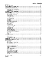
Page 1: ...the machine or to other property could occur as well you must have training in the operation of this machine before using it If you or your operator s cannot read English have this manual explained fully before attempting to operate this machine Si Ud o sis operadores no pueden leer el Inglés se hagen explicar este manual completamente antes de tratar el manejo o servicio de esta máquina Part No 2...

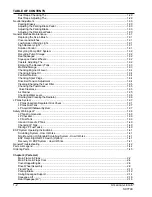
Page 2: ...arging System Light 1 18 High Recovery Light 1 18 Low Solution Light 1 18 Hopper Safety Arm 1 19 To Engage Safety Arm 1 19 Seat Position Adjustment 1 19 Directional Control Pedal 1 19 Hydraulic Reservoir Level Sight Gauge 1 20 Horn Button 1 20 Choke 1 20 Operating Instructions 1 21 Pre Start Checklist 1 21 Starting Gas Machines 1 21 Starting LP Machines 1 21 Post Operation Checklist 1 21 Service C...

Page 3: ...Fuel Filter 1 35 Checking the Fuel Hoses 1 35 Valve Clearance 1 35 Air Cleaner 1 35 Checking Water Level 1 36 Draining and Cleaning the Radiator 1 36 LP Gas System 1 37 LP Gas Vaporizer Regulator Qick Check 1 37 LP Gas Fuel Tank 1 37 LP Liquid Withdrawal System 1 37 Safety Warnings LP 1 38 LP Tank Components 1 39 LP Checklist 1 39 LP Fuel Tank 1 39 Use and Care of LP Tank 1 40 Changing LP Tank 1 4...

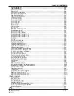
Page 4: ...72 Hydraulic Hoses Fittings cont 2 74 Drive Steering Motor 2 76 Scrub Deck Motors Lift Cylinder 40 2 78 Scrub Deck Motors Lift Cylinder 46 2 79 40 46 Scrub Deck Connections 2 80 Squeegee Lift Cylinder 2 81 Dust Control Hydraulic Motor 2 82 Solution Vacuum Hydraulic Motor 2 83 Low Dump Hopper Cylinder 2 84 Main Side Broom Hydraulic 2 85 Hydraulic Connection Diagram 2 86 Seat Support 2 88 Decals 2 9...

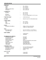
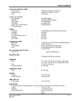
Page 5: ...S Front Solid Urethane Two 2 16 in 41cm x 3 75 in 8 26 cm Rear Solid Rubber One 1 16 in 41 cm x 4 00 in 10 16cm RAMP CLIMBING Transporting 12 Operating 6 INSTRUMENTS AND CONTROLS Main Side Broom Switch Key Switch Low LP Indicator Light Hour Meter Squeegee Switch Fuel Gauge Recovery Tank Full Light Choke Scrub Deck Switch Dust Control Switch with certain models Horn Button Low Solution Light Soluti...

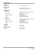
Page 6: ... Pressure Compensated Variable Displacement Reservoir 9 5 Gal 35 9 liter Control Valves Electro Hydraulic with 10 Solenoids Fluid Mobil MultipurposeATF or Equivalent Dexron III Fluid SOLUTION RECOVERY SYSTEM Vacuum Fan Impellor Hydraulic Drive RECOVERYTANK 78 Gallons 295 liter Polyethylene SQUEEGEE Rear Accu Trac 40 in 101 6 cm Swing break away Accu Trac 46 in 116 8 cm Swing Break Away Side 26 in ...

Page 7: ...n 68mm x 68mm HP 24 5 3600 RPM Oil Capacity Displacment 45 2 cu in 740 cc Fuel StandardAutomotive Gasoline Coolant 50 50 Ethylen Glycol and Water Kubota DF1005 Type Vertical Water Cooled Four 4 Cylinder LP Engine Bore and Stroke 2 68in x 2 68in 68mm x 68mm HP 24 5 3600 RPM Oil Capacity Displacment 45 2 cu in 740 cc Fuel StandardAutomotive Gasoline Coolant 50 50 Ethylen Glycol and Water FUEL SYSTEM...

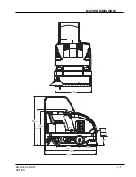
Page 8: ...American Lincoln 1 7 SC7740 MACHINE DIMENSIONS 47 0in 119 3 cm 14 3in 36 3 cm 27 9in 70 8 cm 38 6in 98 1 cm 87 0in 220 9 cm 87 9in 223 4 cm 55 8in 141 8 cm 59 9in 152 2 cm 81 2in 206 2 cm ...

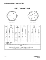
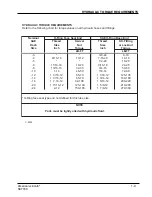
Page 9: ...135 239 387 579 15 28 43 108 17 31 49 76 110 153 267 130 22 40 63 95 138 191 338 545 818 151 24 44 70 108 155 216 378 18 33 47 114 19 34 55 85 20 35 54 132 22 39 62 95 5 9 13 32 6 10 16 20 37 49 120 23 41 64 156 21 34 49 120 C C C C F F F F C Coarse Thread F Fine Thread Torque values for 6 through 1 4 are lb in All others are lb ft NOTE Decrease the torque by 20 when using thread lubricant The tor...

Page 10: ...Size Inch Torque Inch Torque LB FT LB FT 3 3 8 24 8 10 4 9 16 18 10 12 7 16 20 14 16 5 1 2 20 18 20 6 11 16 16 18 20 9 16 18 24 25 8 13 16 16 32 35 3 4 16 50 60 10 1 14 46 50 7 8 14 72 80 12 1 3 16 12 65 70 1 1 16 12 125 135 14 1 3 16 12 65 70 1 3 16 12 160 180 16 1 7 16 12 92 100 1 5 16 12 200 220 20 1 11 16 12 125 140 1 5 8 12 210 280 24 2 12 150 165 1 7 8 12 270 360 O Ring face seal type end no...

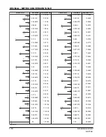
Page 11: ...4375 0 359375 0 375 0 390625 0 40625 0 421875 0 4375 0 453125 0 46875 0 484375 05 0 515625 0 53125 0 546875 0 5625 0 578125 0 59375 0 609375 0 625 0 640625 0 65625 0 671875 0 6875 0 703125 0 71875 0 734375 0 75 0 765625 0 78125 0 796875 0 8125 0 828125 0 84375 0 859375 0 875 0 890625 0 90625 0 921875 0 9375 0 953125 0 96875 0 984375 1 00 0 3969 0 7938 1 1906 1 5875 1 9844 2 3813 2 7781 3 1750 3 57...

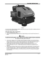
Page 12: ...f operating hours before the initial oil change is the same as normal After the first 50 operating hours service must be performed on your engine to ensure future high performance and trouble free operation See Maintenance 4 Check radiator coolant level Permanent type antifreeze is added at the factory to provide protec tion to approximately 35 F 37 C To retain this protection level always add par...

Page 13: ...S CAUTIONSANDNOTES WARNING Machines can ignite flammable materials and vapors Do not use with or near flammables such as gasoline grain dust solvents and thinners WARNING Improper use of heavy machinery can cause personal injury WARNING Operate only when lids doors and access panels are securely closed WARNING Use care when reversing machine in confined area WARNING When servicing the machine disc...

Page 14: ...chine Keep hands and feet on the designated controls Always operate in well lighted areas WARNING Do not carry passengers on the machine Set the Wheel Lock when leaving the machine Chock block the wheels if the machine is parked on a grade ramp or is being prepared for Maintenance WARNING Never leave the operator s compartment when the is engine running WARNING Report damage or faulty operation im...

Page 15: ...NS INCLUDINGAREAS OF VOLATILE DUST OR VAPOR CONCENTRATIONS Operators must be trained and qualified to operate this machine They must also understand the operator s manual before starting Use caution when mounting or dismounting the machine particularly on wet slippery surfaces Do not dump the hopper over an open pit or dock Do not dump the hopper when positioned on a grade ramp The machine must be...

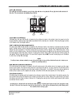
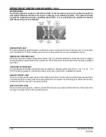
Page 16: ...r to avoid dust filter damage NOTE The filter shaker will automatically run each time the broom is turned off and the DustControl is in Auto mode switch is in middle position MAIN BROOM SIDE BROOM SWITCH The main side broom switch is located on the left side console in the bottom bank By pressing in the upper portion of the switch the side and main broom are raised and turned off To lower and turn...

Page 17: ...y raise again with the vacuum on a 15 second delay When the machine is once again placed in the forward position the squeegee will lower and the vacuumautomatically turns on In pressing the lower portion of the switch a manual override is engaged allowing the squeegee and vacuum system to operate independent of the scrub deck Again if the machine is placed in reverse the squeegee automatically rai...

Page 18: ...LIGHT The fuel gauge or LP indicator light is located on the instrument panel to the left of the hour meter and indicates the level of fuel in the tank or low LP indicator light The key switch powers the fuel gauge The key switch must be in the ON position for the fuel gauge to work The fuel gauge is not included on machines that use Liquid Propane fuel BACK UP ALARM SWITCH Option The back up alar...

Page 19: ...t to indicate low oil pressure When this occurs have the SC7740 serviced by a qualified technician CHARGING SYSTEM LIGHT The charging system battery light illuminates to indicate a charging system fault When this occurs the SC7740 charging system is not working properly and must be serviced by a qualified technician HIGH RECOVERY LIGHT The recovery high warning light located on the lefthand side o...

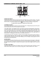
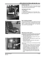
Page 20: ...e operator s area This pedal controls the machine direction 1 Apply foot pressure on the right side of the pedal to move the machine forward 2 Increase foot pressure on the right side of the pedal to increase the forward speed 3 Apply foot pressure on the left side of the pedal to move the machine in reverse 4 Increase the pressure on the left side of the pedal to increase the reverse speed The Di...

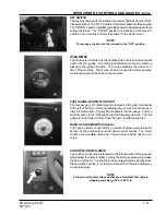
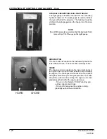
Page 21: ...orn button is located on the instrument panel in the lower lefthand corner The horn button is always active CHOKE The choke control is located on the instrument panel to the right of the horn button and is used to aid in starting the engine The choke governs the mixture of air and fuel during the combustion cycle of engine operation The choke should be pulled while starting the engine and then gra...

Page 22: ...ne at no more than throttle with the machine standing still for 5 10 minutes to warm the engine and hydraulic oil STARTING GAS ENGINES Use the choke in extremely cold temperatures under 32 F or 0 C 1 Pull choke if needed 2 Set the engine speed control to idle setting 3 Turn key to START position until engine starts then release The key switch will return to the I position 4 Push in the choke after...

Page 23: ...ery electrolyte level unless maintenance free battery 25 Check all hydraulic hoses for wear or cuts 26 Rotate main brush end over end 27 Clean or replace panel filters 28 Lubricate dump system and drive wheel pivot points Perform recommended engine maintenance see engine manual if applicable 100 HOUR MAINTENANCE CHECKLIST 29 Change crankcase oil 30 Change engine oil filter 31 Lubricate drive wheel...

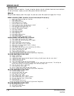
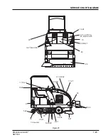
Page 24: ...1 23 SC7740 SERVICE CHART DIAGRAM Figure 23 1 7 27 2 11 12 15 16 23 25 43 44 45 10 36 38 41 46 26 14 24 3 47 48 49 50 35 35 35 8 9 19 20 17 18 40 4 13 37 42 29 30 5 22 32 34 28 33 35 28 31 6 21 6 21 5 22 39 C2144a 0602 ...

Page 25: ...p and scrub paths This will eliminate leaving dirty patches 4 Do not turn steering wheel too sharply when the machine is in motion The machine is very responsive to movement of the steering wheel so avoid sudden turns 5 Try to follow as straight a path as possible Avoid bumping into posts or scraping the sides of the machine 6 Always allow the machine to warm up before operating in cold temperatur...

Page 26: ...e batteries before doing any maintenance Keep all fasteners tight Keep adjustments according to the specifi cations as shown in the Service Manual for this machine WARNING Always wear eye protection and protective clothing when working near batteries Do not put tools or other metal objects across the tops of the batteries NO SMOKING WARNING The hopper could fall and cause serious injury Always eng...

Page 27: ...s closed WARNING Engage hopper safety arm while accessing the main broom REPLACING THE MAIN BROOM The Main Broom should be replaced when the bristles become worn to less than 3 The main broom is held in place by a removable broom idler arm This feature provides for easy removal and installation of the main broom without the need for special tools or equipment Follow the instructions below for main...

Page 28: ...ockwise to INCREASE the sweep pattern width Turn the adjustment knob clockwise to DECREASE the sweep pattern width REPLACING THE SIDE BROOM Change the side brooms when the bristles become worn to less than 3 1 Park the machine on a smooth level surface turn key switch to O Position and engage parking brake 2 Place broom switch in the UP position 3 Remove the lock pin which holds the broom flange t...

Page 29: ... tear in the filter media will allow dirt to pass through the filter and can be easily seen as a dirty patch on the top side on the filter Cleaning of the filter is necessary when the filter shaker fails to adequately clean the pleats CHECKING THE DUST CONTROL FILTER 1 Park the machine on a smooth level surface turn the key switch to the O position and engage the parking brake 2 Raise the engine h...

Page 30: ...amage and should be inspected daily and maintained in good condition CHECKING THE DUST FLAPS The dust flaps are used on the wheel well broom chamber and broom door Inspect the flaps daily and replace any flap that shows signs of wear or deterioration All flaps should be replaced when worn or damaged to the point that they can no longer perform their normal function The adjustable flaps have slotte...

Page 31: ...eels They are operated by the brake pedal and the lock lever Check the parking brakes daily for proper operation and inspect the brake pads for wear every 100 hours of operation ADJUSTING THE PARKING BRAKE PEDAL Perform this adjustment to ensure proper pedal height and linkage operation The brakes are properly adjusted when the brakes hold theSC7740 on an 6 degree ramp The brakes need adjusted if ...

Page 32: ...part of the level control system requires no maintenance If the system fails to operate consult the Electrical Troubleshooting Guide HIGH RECOVERY WARNING LIGHT The high recovery warning will illuminate approximately 5 minutes before loss of vacuum to the recovery tank This part of the level control system requires no maintenance except for daily cleaning of the tank level switch If the system fai...

Page 33: ...es or caster wheels The squeegee blades are designed to flip over and use another unworn edge To service the blades 1 Loosen the clamp bolts which clampsqueegee tool together 2 Loosen far enough to slip the end clamp brackets off the squeegee tool This will allow flipping the blades or installing new blades 3 Install blades so that the outer blade is 3 16 longer than the inner blades This is achie...

Page 34: ...0 days should be completely drained of fuel to prevent gum deposits from forming on essential carburetor parts fuel filter and tank The use of a fuel additive such as STA BIL or an equivalent will minimize the formation of fuel gum deposits during storage Such an additive may be added to the gasoline in the fuel tank of the engine The following procedures should be used to prepare the machine for ...

Page 35: ...il filter cartridge remove cartridge with a filter wrench apply film of engine oil to the rubber gasket on the new cartridge and screw in by hand WARNING Overtightening may cause deformation of the rubber gasket After the cartridge has been replaced engine oil normally decreases a little Check the oil level and add new oil to the specified level NOTE After the cartridge has been replaced the engin...

Page 36: ...RANCE Check every 800 hours of use 1 Loosen the lock nut and the adjusting screw on the rocker arm 2 Turn the adjusting screw to adjust the valve clearance at the top dead center T D C during the compres sion stroke of the piston To get the T D C find piston s TC mark on the flywheel and align it to punchmark line on the rear end plate 3 Tighten the lock nuts and check the valve clearance again af...

Page 37: ...o pure water When cleaning the system KUBOTA Detergent No 20 is recommended to effectively wash away the rust buildup WARNING Never remove the radiator cap under any conditions while engine is operating Failure to follow these instruc tions could result in personal injury and or damage to the cooling system To avoid having scalding hot coolant or steam blow out of the radiator use extreme care whe...

Page 38: ...et or may have developed a pinhole leak allowing the LP fuel to enter the cooling system LP GAS FUEL TANK The LP tank is located under the driver s seat Use only the proper size and type of LP tank The SC7740 LP powered sweeper scrubber uses a 33 5 lb Liquid withdraw tank The DOT designation of the tank is DOT 4BW 240 LP LIQUID WITHDRAWAL SYSTEM The liquid LP fuel flows from the LP tank under its ...

Page 39: ...the LP tank is securely mounted on the machine with the retainer bracket clamping the tank and with the locating pin in position WARNING Make sure service coupling is clean and free of damage Make sure service coupling of tank matches machine servicing coupling WARNING Park the machine in a shaded cool area when not in use WARNING Keep the LP tank service valve closed when the tank is not in use W...

Page 40: ... liquid or vapor the manufacturer the date of manufacture the capacity the weight and the date of requalification D O T fuel tanks must be requalified checked periodi cally This requalification must be recorded and maintained for the life of the container LP fuel tanks are equipped with the following approved valves and fittings Safety Relief Valve This is a spring loaded valve that relieves exces...

Page 41: ...ding device 6 Inspect the tank and tank fittings for damage or abnormal wear Handle the tank carefully It must not be dropped or mishandled 7 Store the LP tank in a designated safe area 8 Select a full LP tank and observe for damage or leaks 9 Carefully install the full tank in the machine so the tank centering pin enters the aligning hole in the tank collar This assures that the tank is positione...

Page 42: ...bing the dirty solution is vacuumed from the floor and discharged into the recovery tank Sensors in each tank will indicate by lights on the control panel when the water in the solution tank is too low or when the water in the recovery tank is too high THE ESP RECYCLING SYSTEM ON OFF SWITCH Option This switch turns the ESP recycling system on and off NOTE The solution control lever must be on FULL...

Page 43: ...7 Vacuum float shut off 1 Side squeegee blades poor contact with floor 2 Squeegee blades worn or damaged 3 Too much solution being applied before making turns REMEDY 1 Lower hopper 2 Adjust hopper switch 1 Examine rubber blades for cuts or worn spots Replace if necessary 2 Check seal on recovery tank 3 Disconnect hoses from squeegee flush both thoroughly 4 Check all hose connections for looseness ...

Page 44: ...d 1 Directional Control Pedal and or linkage jammed or not adjusted 1 Check pedal linkage 2 Front wheels jammed or brakes locked 2 Check wheels and brakes 3 Hydraulic pump trouble 3 Check repair pump 4 Rear wheel hydraulic motor broken shaft key broken shaft etc 4 Check repair Machine Moves Slowly 1 Low hydraulic fluid 1 Add oil to the reservoir 2 Brake dragging 2 Check brakes 3 Hydraulic oil temp...

Page 45: ... Hexagonal Socket Flat Head Cap Screw KNH Knurled Head Screw MHHC Metric Hexagon Head Cap Screw PHM Pan Head Machine Screw RHD Round Head Drive Screw RHM Round Head Machine Screw RHW Round Head Wood Screw SHC Shiny Crown Cap Screw SHTB Shoulder Thumb Screw SQ Square Head Screw TB Thumb Screw THM Truss Head Machine Screw WELD Weld Stud WG Wing Screw ABBREVIATIONS SETSCREWS HS Hexagonal Socket Setsc...

Page 46: ...s listed in this manual can be ordered from the following address 1 Use the model number catalog number and serial number when ordering 2 Give the part number description and quality of parts needed 3 Give shipping instructions for either freight UPS or parcel post Parts and supplies listed in this manual can be ordered from the following address American Lincoln American Lincoln Distributor Ameri...

Page 47: ...1 46 American Lincoln SC7740 NOTES ...

Reviews: