
1-44
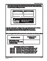
American-Lincoln
®
SC7740
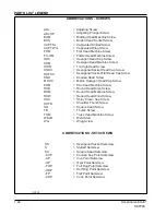
PARTS LIST LEGEND
ABBREVIATIONS - SCREWS
ADJ
= Adjusting Screw
ADJ.SP
= Adjusting Plunger Screw
BHM
= Binding Head Machine Screw
BHS
= Button Head Socket Screw
CAPT.SL
= Captivated Slotted Screw
CAPT.WG
= Captivated Wing Screw
FHM
= Flat Head Machine Screw
FIL.HM
= Filister Head Machine Screw
HHC
= Hexagon Head Cap Screw
HHM
= Hexagon Head Machine Screw
HIHD
= 1/2 High Head Screw
HSHC
= Hexagonal Socket Head Cap Screw
HSFHC
= Hexagonal Socket Flat Head Cap Screw
KNH
= Knurled Head Screw
MHHC
= Metric Hexagon Head Cap Screw
PHM
= Pan Head Machine Screw
RHD
= Round Head Drive Screw
RHM
= Round Head Machine Screw
RHW
= Round Head Wood Screw
SHC
= Shiny Crown Cap Screw
SHTB
= Shoulder Thumb Screw
SQ
= Square Head Screw
TB
= Thumb Screw
THM
= Truss Head Machine Screw
WELD
= Weld Stud
WG
= Wing Screw
ABBREVIATIONS - SETSCREWS
HS
= Hexagonal Socket Setscrew
S
= Slotted Setscrew
SH
= Square Head Setscrew
-KCP
= Knurled Cup Point Setscrew
-CP
= Cup Point Setscrew
-OP
= Oval Point Setscrew
-FDP
= Full Dog Point Setscrew
-HDP
= Half Dog Point Setscrew
-FP
= Flat Point Setscrew
-COP
= Cone Point Setscrew
C-2004


