Rev. 5
105
Remote Interface Reference
SCPI Status System
An
event
register latches various events. Events are not buffered, therefore
once a bit is set in the event register, further occurrences of that event are
ignored. Once a bit is set in an event register, the bit remains set until the
register is read (
*ESR?
) or a
*CLS
(clear status) command is issued. A
query of an event register returns a decimal value in the appropriate
output buffer which corresponds to the binary-weighted sum of all bits set
in the register.
An
enable
register (or bitmask) defines which bits in an event register are
reported to the Status Byte register group. An enable register can be both
written and queried. The
*CLS
(clear status) command does not clear an
enable register. To enable or disable bits in an enable register, write a
decimal value which corresponds to the binary-weighted sum of the bits
you wish reported to the Status Byte register.
4.2.2.1
Status Byte Register
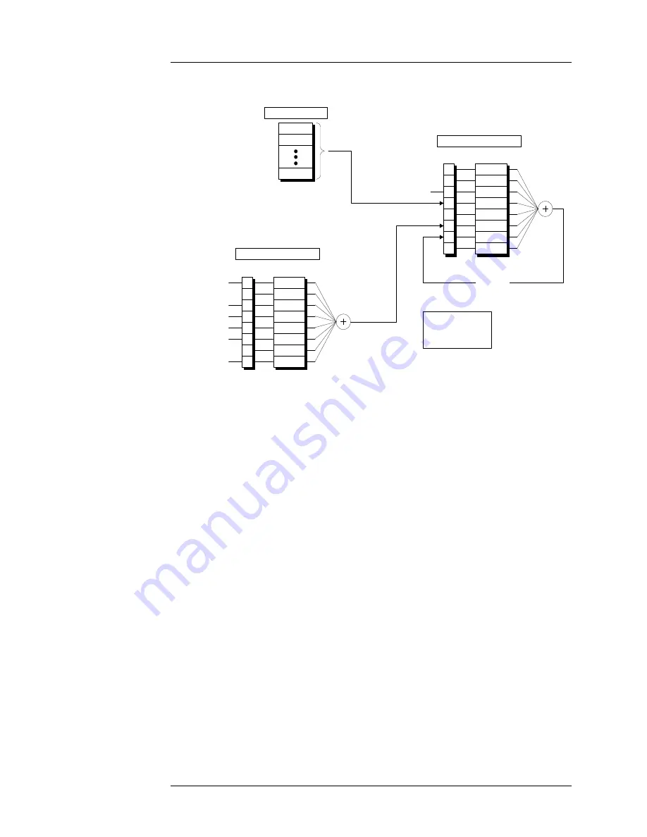
The Status Byte register group reports conditions from the Standard Event
register or output buffers. Data in the output buffer is immediately reported in
the “Serial Message Available” bit (bit 3). Clearing a bit in the Standard Event
register will update the corresponding bit in the Status Byte register,
according to the Standard Event enable register. Reading the pending
0
1
2
3
4
5
6
7
<1>
<2>
<4>
<8>
<16>
<32>
N/A
<128>
*SRE <
value
>
*SRE?
Serial Poll
*STB?
C
EN
Summary Bit
"OR"
Status Byte Register
0
1
2
3
4
5
6
7
<1>
<2>
<4>
<8>
<16>
<32>
<64>
<128>
*ESE <
value
>
*ESE?
*ESR?
EV
EN
"OR"
Standard Event Register
Operation Complete
Query Error
Device Error
Execution Error
Command Error
Power On
Quench Condition
Serial Output Buffer
NOTES:
C = Condition Register
EV = Event Register
EN = Enable Register
Figure 4-1.
The Model 430 Programmer Status System.
Summary of Contents for 05100PS-430-601
Page 2: ......
Page 10: ...x Rev 5 List of Figures ...
Page 12: ...xii Rev 5 List of Tables ...
Page 18: ...xviii Rev 5 Foreword Safety Summary ...
Page 30: ...12 Rev 5 Introduction Operating Characteristics ...
Page 42: ...24 Rev 3 Installation Power Up Procedure ...
Page 114: ...96 Rev 5 Operation Summary of Operational Limits ...
Page 156: ...138 Rev 5 Remote Interface Reference Error Messages ...
Page 168: ...150 Rev 5 Service Return Authorization ...
Page 226: ...208 Rev 5 Index ...


