R
EV
9
93
A
MERICAN
M
AGNETICS
, I
NC
.
O
PERATION
: S
ETUP
S
UBMENU
D
ESCRIPTIONS
: P
ROTECTION
S
UBMENU
Ic
is always displayed in Amperes. This default display option is
illustrated below along with an illustration of the status indicator
indicating a temperature-limited condition (i.e. the reverse-video
T character):
To remove the
Ic
and/or temperature display, simply press the left
or right arrow key again.
I
C
S
LOPE
This value sets the
Ic Slope
parameter in Amperes/Kelvin. Note
that for superconducting magnets, the slope value will be
negative since the maximum current density increases with
decreasing temperature.
I
C
O
FFSET
This value sets the
Ic Offset
parameter in Amperes. This value
shifts the entire
Ic
line by a current offset. A higher offset value
will increase the value of
Ic
for a given temperature.
T
MAX
This value is a maximum allowable system temperature as
measured via the Auxiliary Input channel 3 in Kelvin. The Model
430 Programmer will limit entry of the Target Field/Current
Setpoint to a value of zero if the present temperature exceeds
T
max
. If the Protection Mode is set for “Cont f(T)”, then
the
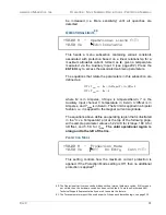
+50.53 A
T
Mode: Ramping: Ic=50.5
4.50 K
No PSwitch Installed
Illustration of optional default display showing the value of
I
c
, the present Aux-In
3 temperature, and a temperature-limited condition.
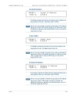
+50.00 A — Ic Slope (A/K)
+0.50 Vs
-22.000
+50.00 A — Ic Offset (A)
+0.50 Vs
+150.000
+50.00 A — Tmax (K)
4.50 K
6.000
Summary of Contents for 430
Page 2: ......
Page 16: ...XVI REV 9 AMERICAN MAGNETICS INC FOREWORD SAFETY SUMMARY ...
Page 28: ...12 REV 9 AMERICAN MAGNETICS INC INTRODUCTION OPERATING CHARACTERISTICS ...
Page 64: ...48 REV 9 AMERICAN MAGNETICS INC INSTALLATION POWER UP AND TEST PROCEDURE ...
Page 208: ...192 REV 9 AMERICAN MAGNETICS INC SERVICE RETURN AUTHORIZATION ...
Page 248: ...232 REV 9 AMERICAN MAGNETICS INC APPENDIX SHORT SAMPLE MODE ...


