122
R
EV
9
A
MERICAN
M
AGNETICS
, I
NC
.
O
PERATION
: R
AMPING
F
UNCTIONS
E
XAMPLE
Point 6
. The target field/current setting of +40.000 A is achieved and the
Model 430 Programmer switches to HOLDING mode. At this point the
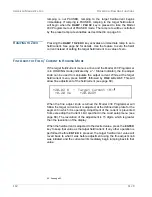
user deactivates the persistent switch heater by pressing the
PERSIST.
SWITCH CONTROL
key, which removes the magnet from the circuit.
Point 6a
. The dashed line between point 6a and 6b is the rapid ramping
down of the power supply current which automatically happens after the
PSwitch Cooled Time has elapsed. Note that the magnet current
remains at the Point 6 value when the magnet was placed in persistent
mode.
Point 6c
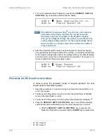
. The user presses the
PERSIST. SWITCH CONTROL
key
which rapidly ramps the power supply output to the current that is flowing
in the magnet. The power supply matches the magnet current at point
6d.
Point 7
. The user again increases the ramp rate and presses the
RAMP
TO ZERO
key to begin ramping to zero current. The Model 430
Programmer automatically ramps the current to 0 A.
Point 8
. The Model 430 Programmer switches to ZERO CURRENT
mode at 0 A current when achieved and holds at this current until further
commands are issued by the user.
Summary of Contents for 430
Page 2: ......
Page 16: ...XVI REV 9 AMERICAN MAGNETICS INC FOREWORD SAFETY SUMMARY ...
Page 28: ...12 REV 9 AMERICAN MAGNETICS INC INTRODUCTION OPERATING CHARACTERISTICS ...
Page 64: ...48 REV 9 AMERICAN MAGNETICS INC INSTALLATION POWER UP AND TEST PROCEDURE ...
Page 208: ...192 REV 9 AMERICAN MAGNETICS INC SERVICE RETURN AUTHORIZATION ...
Page 248: ...232 REV 9 AMERICAN MAGNETICS INC APPENDIX SHORT SAMPLE MODE ...


