R
EV
9
63
A
MERICAN
M
AGNETICS
, I
NC
.
O
PERATION
: SHIFT+
KEY
C
OMMANDS
/ M
ENUS
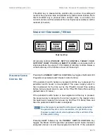
In general, a SHIFT+key command is executed or a menu is accessed
by first pressing the
SHIFT
key (which turns on the
SHIFT
LED), and
then pressing
11
one of the keys of the numeric keypad (
0
through
9
, “
.
”,
or “
+/-
”). The SHIFT+key command / menu for each key of the numeric
keypad is shown in light blue text at the top of each key.
To access the voltage limit menu, for example, press the
SHIFT
key, and
then press the
VOLTAGE LIMIT
key (also the
2
key). Note that some of
the SHIFT+key menus can also be accessed using the setup menu.
Pressing the
ESC
key or the
SHIFT
key a second time will clear the
SHIFT
function and return the keypad to it's numeric function.
R
AMP
R
ATE
(S
HIFT
+
1)
Use of the
RAMP RATE
(SHIFT+1) key provides a menu for setting
ramp rate(s). The ramp rate may be set
12
within the range specified for
the specific Model 430 Programmer configuration (refer to the
specifications on page 7). If field units are being used, then the ramp rate
setting is displayed and set in units of kG/sec or T/sec).
The allowable range is defined by the setting of the coil constant and the
allowable range of the ramp rate in terms of current as specified in the
table on page 7. If the Ramp Segments value
13
is greater than 1, then
the menu also allows setting of the field or current range for each ramp
rate segment.
The Model 430 Programmer will ramp at the specified rate if the
available compliance of the power supply is sufficient and the Voltage
Limit is not exceeded. The Model 430 automatically decreases the ramp
rate internally during operation if either the available compliance of the
power supply is insufficient, or the Voltage Limit is active.
R
AMP
R
ATE
E
XAMPLE
An example (using a magnet with rated current of 60 A
14
) will
illustrate the use of the ramp rate menus. The example assumes
that the field/current units have been set to amperes and the
ramp segments value has been set to three (3) segments. The
ramping is chosen with rates as follows:
1. ±0.2 A/s from 0 to ±55 A
2. ±0.1 A/s from ±55 to ±58 A
3. ±0.05 A/s above ±58 A.
11. Note the SHIFT key plus the following key-press are sequential, not simultaneous.
12. Using numerical keys as described on page 54 or the fine adjust knob (page 55).
13. See page 95.
14. In this example, the Current Limit is set at the rated magnet current of 60 A.
Summary of Contents for 430
Page 2: ......
Page 16: ...XVI REV 9 AMERICAN MAGNETICS INC FOREWORD SAFETY SUMMARY ...
Page 28: ...12 REV 9 AMERICAN MAGNETICS INC INTRODUCTION OPERATING CHARACTERISTICS ...
Page 64: ...48 REV 9 AMERICAN MAGNETICS INC INSTALLATION POWER UP AND TEST PROCEDURE ...
Page 208: ...192 REV 9 AMERICAN MAGNETICS INC SERVICE RETURN AUTHORIZATION ...
Page 248: ...232 REV 9 AMERICAN MAGNETICS INC APPENDIX SHORT SAMPLE MODE ...


