R
EV
9
53
A
MERICAN
M
AGNETICS
, I
NC
.
O
PERATION
: M
ODEL
430 P
ROGRAMMER
D
EFAULT
D
ISPLAY
S
TATUS
I
NDICATOR
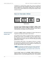
The status indicator displays
the Model 430 Programmer
operating status. It is always
visible (except during a quench
condition) and is displayed just
to the right of the field / current
display (see the figure on
page 51). The status indicator
may be one of the symbols
indicating a condition as
described in the table at left.
If the ramping mode character
is blank, then a quench
condition exists and the red
MAGNET QUENCH
LED on
the
front
panel
will
be
illuminated.
See page 110 for a more detailed discussion of the meaning of the
ramping modes (Paused, Ramping Up, Ramping Down and Holding).
M
AIN
D
ISPLAY
The default main display (the rightmost portion of the display – see the
figure on page 51) shows either a voltmeter indicating magnet voltage or
ramp mode and persistent switch heater state. Ramp mode is displayed
on the top line of the main display; it will be one of ten states, as listed in
the table on page 111.
The persistent switch heater state is displayed on the bottom line of the
main display. If the Model 430 Programmer has been setup for use with
a persistent switch, it will indicate either ON or OFF for the persistent
switch heater state; otherwise, it will display “No PSwitch Installed.”
Description of Status Indicators
P
Paused
Ramping Up
Ramping Down
–
Holding
Heating Persistent Switch
Cooling Persistent Switch
V
Voltage Limited
C
Current Limited
T
Temperature Limited
Summary of Contents for 430
Page 2: ......
Page 16: ...XVI REV 9 AMERICAN MAGNETICS INC FOREWORD SAFETY SUMMARY ...
Page 28: ...12 REV 9 AMERICAN MAGNETICS INC INTRODUCTION OPERATING CHARACTERISTICS ...
Page 64: ...48 REV 9 AMERICAN MAGNETICS INC INSTALLATION POWER UP AND TEST PROCEDURE ...
Page 208: ...192 REV 9 AMERICAN MAGNETICS INC SERVICE RETURN AUTHORIZATION ...
Page 248: ...232 REV 9 AMERICAN MAGNETICS INC APPENDIX SHORT SAMPLE MODE ...

