Chapter 4 Installation
32
Step 7 Connect the Cables,
Continued
Serial Connector
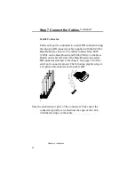
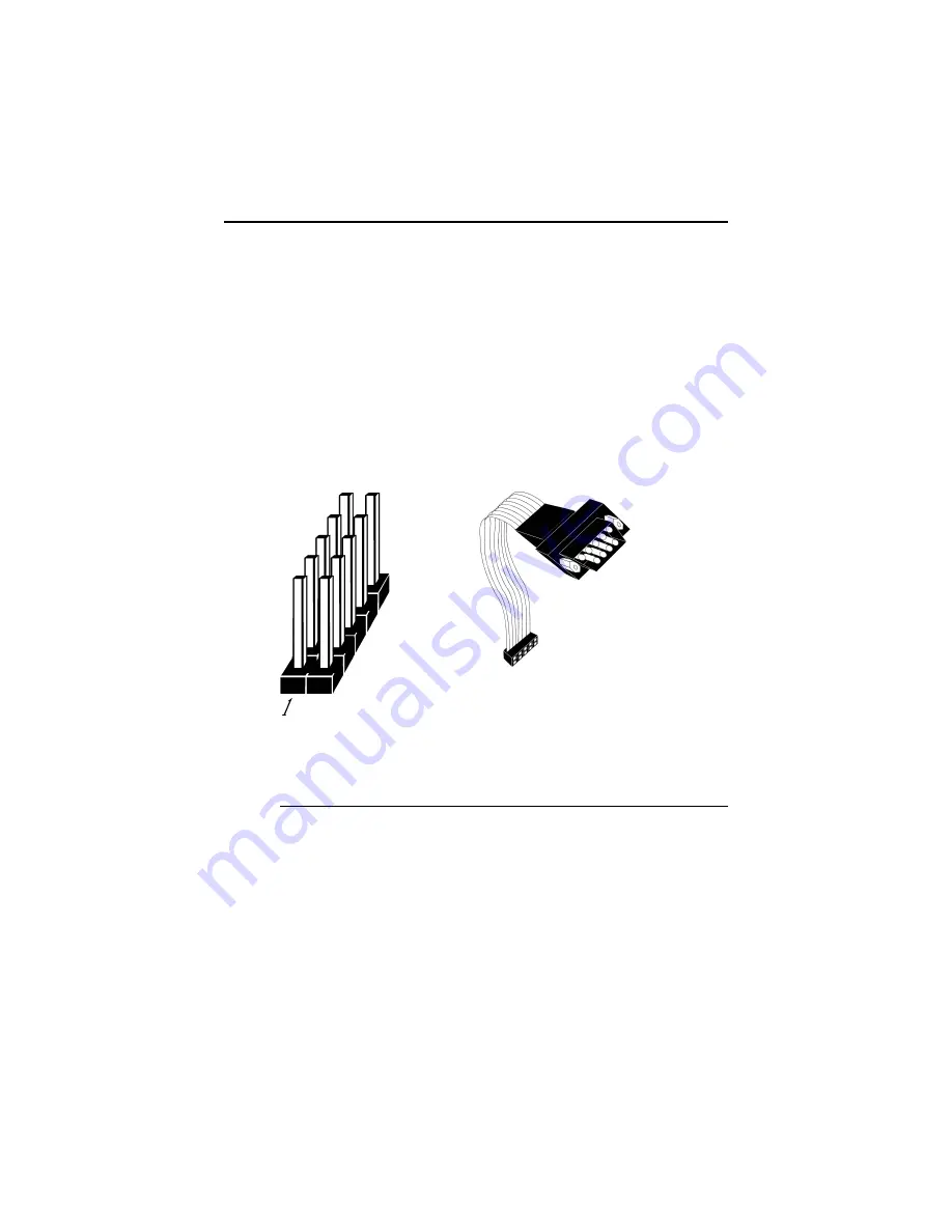
Each serial port is connected to a serial DB connector using
the nine-pin DB connector cable supplied with the EZ-Flex
Base Board (see below). The cables connect from P007
(COM1 on the Base Board) and P006 (COM2 on the Base
Board) on the far left side of the Base Board to the serial
DB connector attached to the chassis. See page 33 for the
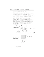
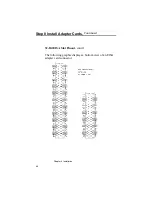
serial port connector pinout. The following graphics depict
a 10-pin serial connector and a serial cable.
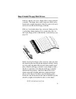
Note the orientation of pin 1 of the connectors. This end of the
connector typically is located near the edge of the cable
with the red stripe on the cable.
Summary of Contents for 28 series
Page 1: ...American Megatrends Inc Series 28 EZ Flex Base Board User s Guide MAN 528 6 18 92 ...
Page 22: ...Chapter 4 Installation 16 ...
Page 55: ...AMI EZ Flex Base Board User s Guide 49 ...
Page 87: ...AMI EZ Flex Base Board User s Guide 81 ...
Page 103: ...AMI EZ Flex Base Board User s Guide 97 ...
Page 118: ...Appendix A EISA Configuration Worksheets 112 ...


