AMI Baby Voyager User's Guide
69
Advanced Chip Set Setup Options,
Continued
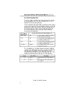
O n B o a r d S e r i a l P o r t 2
O n B o a r d S e r i a l P o r t 2
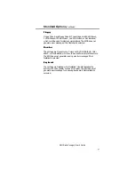
This option enables or disables serial port 2 on the Baby Voyager
motherboard. The settings are I/O Ports 2F8h - 2FFh, I/O Ports 2E8h -
2EFh, or Disabled.
If the configuration data in CMOS RAM is corrupted when the system
is powered on, the system BIOS automatically configures onboard
serial port 2 according to the presence or absence of serial ports on
any adapter cards in the system expansion slots (off board serial
ports). Autoconfiguration only occurs when CMOS RAM data is
corrupted. The result for serial port 2 is:
If the Offboard
Serial Port is
the Onboard Serial Port 2 is Autoconfigured as
None
2F8h
Can be disabled or changed to 2E8h via
BIOS Advanced Chip Set Setup.
2F8h
2E8h
Can be disabled via BIOS Advanced Chip
Set Setup. If changed to 2F8h, an I/O
port address conflict occurs.
2E8h
2F8h
Can be disabled via BIOS Advanced Chip
Set Setup. If changed to 2E8h, an I/O
port address conflict occurs.
2F8h, 2E8h
Disabled
If changed to 3F8h or 3E8h, an I/O port
address conflict occurs.
P4 is serial port 2 on the Baby Voyager motherboard. If disabled
through Setup, do not attach any device to P4 or to any cable attached
to P4. J6 is used to configure the interrupt request line (IRQ) for
onboard serial port 2. The J6 settings are:
Jumper
Pins Shorted
Description
J6
Pins 1-2
IRQ4 selected for onboard serial port 2.
J6
Pins 2-3
IRQ3 selected for onboard serial port 2
(Default).
If onboard serial sort 2 is disabled, remove the jumper block from J6
to disable the onboard serial port 2 interrupt.
Summary of Contents for 39 Series
Page 6: ...Preface vi ...
Page 12: ...Chapter 1 Introduction 6 ...
Page 14: ...Chapter 2 Installation 8 Baby Voyager Layout ...
Page 26: ...Chapter 2 Installation 20 ...

