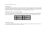
Step 6 Connect the Keyboard
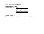
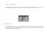
The keyboard connector is a 5-pin DIN socket and is labeled KEYBRD and J3 on the motherboard. It will accept a regular IBM
AT-compatible keyboard. A 5-pin DIN to 6-pin mini DIN converter is needed to connect a PS/2-type keyboard.
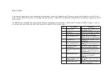
Pin
Assignments
1
Keyboard clock
2
Keyboard data
3
Not used
4
Ground
5
VCC
Step 7 Connect Cables
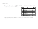
When connecting chassis connectors to the motherboard, connect the correct connector end. Most connector wires are color-
coded. Match the color of the wires leaving the switch or LED to the same pin on the connector end. There may be more than
one connector with the same color-coded wires. If so, follow the wire to the switch or LED. Pin 1 of all connectors is labeled to
identify the pin orientation when plugging in cables.
Summary of Contents for 42 Series
Page 1: ...American Megatrends Inc Series 42 Mark V Baby Screamer 80386 Motherboard User s Guide ...
Page 2: ...MAN 642 Rev C 9 11 92 ...
Page 13: ......
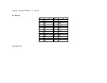
Page 35: ...A29 SA02 B29 5 A30 SA01 B30 OSC A31 SA00 B31 GND ...
Page 59: ......
Page 82: ......
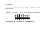
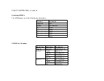
Page 85: ...SRAM Locations ...


