INSTALLATIONS
10
MI802 User’s Manual
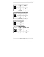
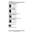
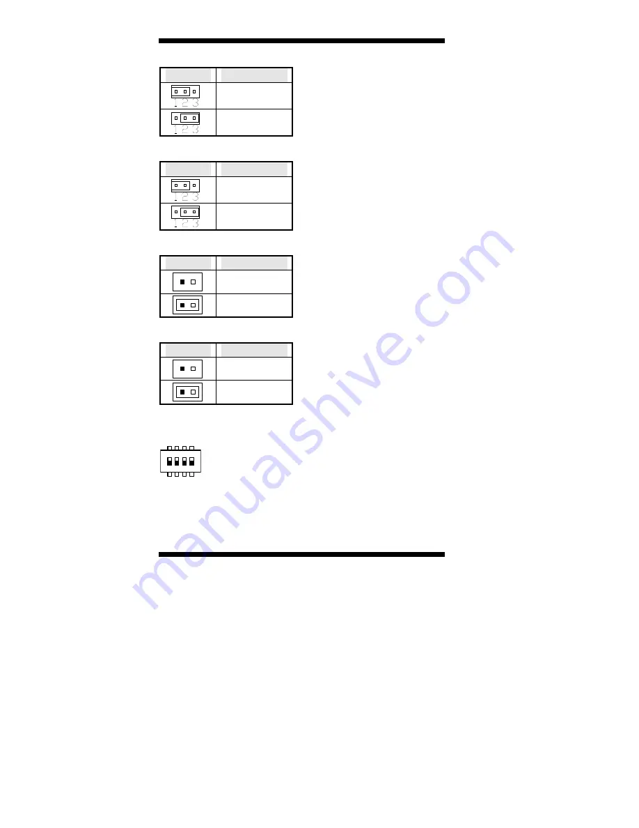
JP5: LCD BackLight Control Selection
JP5
Setting
Super I/O*
Reserved
JP7: Clear CMOS Setting
JP7
Setting
Normal*
Clear CMOS
JP8: LCD BackLight Control Output Level
JP8
Setting
2
1
+3.3V*
2
1
+5V
JP9: LCD Boot ROM Protect (factory use only)
JP9
Setting
2
1
Write
2
1
Normal*
*Default
SW1: Panel Type Selection
1
ON
3
2
4
3
2
1
4
7
8
5
6
Default: Pin 1,2,3,4 OFF(1111)
Summary of Contents for 802
Page 1: ...802 MI802 Intel Cedar Trail NM10 Mini ITX Motherboard USER S MANUAL Version 1 0 ...
Page 4: ...iv MI802 User s Manual This page is intentionally left blank ...
Page 8: ...INTRODUCTION 4 MI802 User s Manual Board Dimensions ...
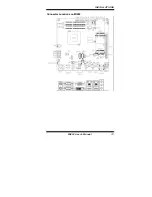
Page 17: ...INSTALLATIONS MI802 User s Manual 13 Connector Locations on MI802 ...
Page 24: ...INSTALLATIONS 20 MI802 User s Manual This page is intentionally left blank ...
Page 50: ...DRIVERS INSTALLATION 46 MI802 User s Manual This page is intentionally left blank ...


