Chapter 1 Hardware Installation
27
Step 5 Attach Power Supply,
Continued
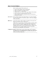
Power Supply Summary You must determine if a power supply meets your electrical and
mechanical requirements. This discussion is only a guideline. You must
perform the power calculation for your system. You can always use a different
power supply for drives. Redundancy and hot swap are system- and customer-
dependent, not basic requirements.
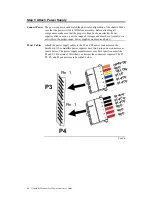
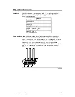
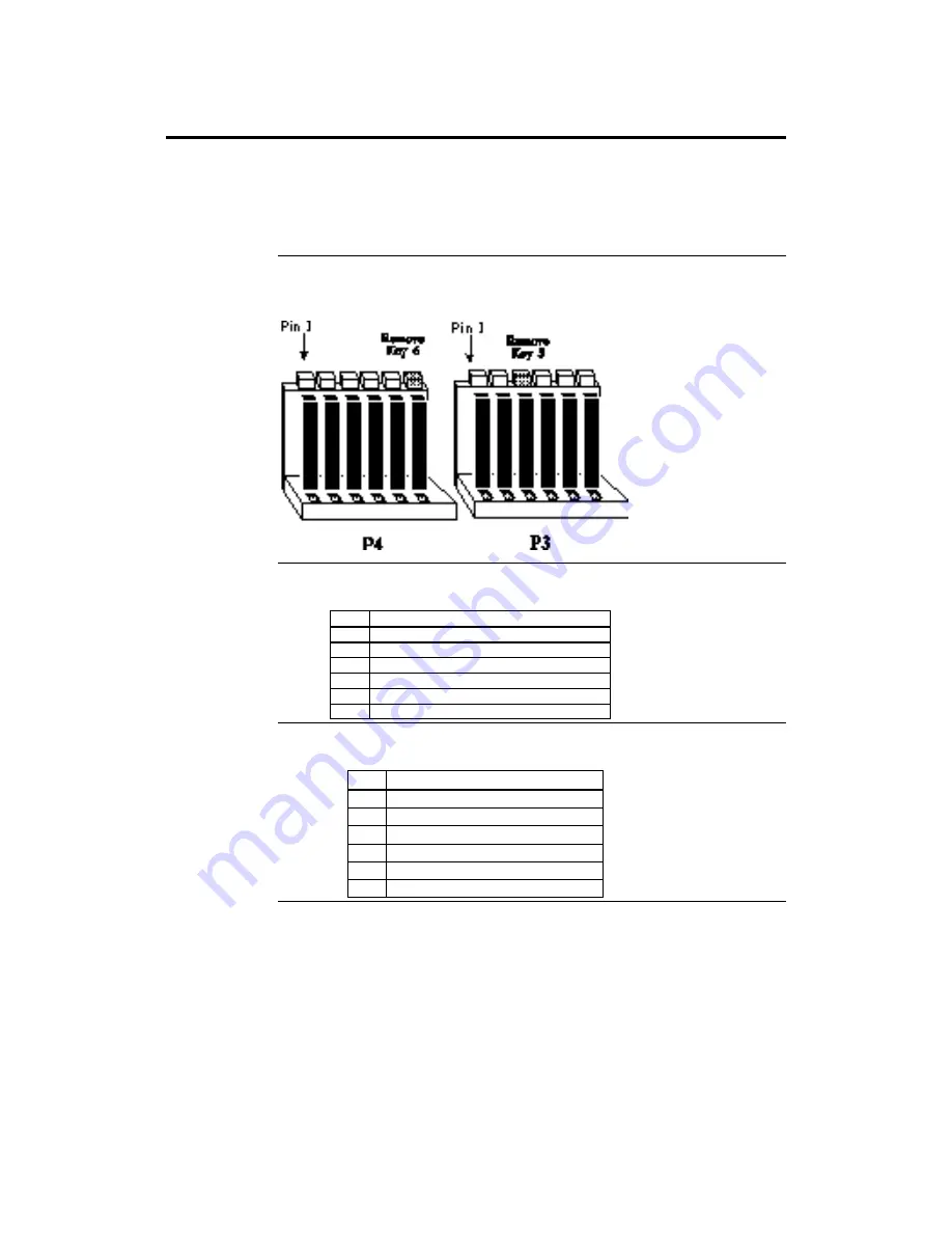
Connector Keys The keys on the connector must be cut to fit on some power supplies, as shown
below.
P3 Pinout
Pin
Description
1
Power Good (Orange wire) (Not used)
2
VCC (Red wire)
3
+12 Volts (Yellow wire)
4
-12 Volts (Blue wire)
5
Ground (Black wire)
6
Ground (Black wire)
P4 Pinout
Pin
Description
1
Ground (Black wire)
2
Ground (Black wire)
3
-5 Volts (White wire)
4
VCC (Red wire)
5
VCC (Red wire)
6
VCC (Red wire)
Summary of Contents for Goliath
Page 1: ...Goliath PCI Quad Pentium Pro EISA System User s Guide MAN 730 6 7 96 ...
Page 45: ......
Page 71: ...Goliath PCI Pentium Pro EISA System User s Guide 66 ...
Page 77: ...Goliath PCI Pentium Pro EISA System User s Guide 72 ...
Page 78: ...Chapter 3 Programming the Flash ROM 73 A Mechanical Drawings ...
Page 79: ...Goliath PCI Pentium Pro EISA System User s Guide 74 ...


