background image

StorTrends® 1300 User’s Guide (StorTrends iTX version 2.7) 

232

Step Description 

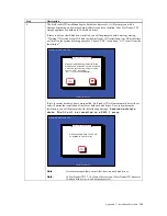
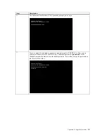
Once you have successfully logged in, you will see the following: 

[root@ITXXXXXXXXXXXXX ~]#  _ 


At the prompt type the following command followed by the <ENTER> key: 

mkdir /mnt/source 


AMI XXX (StorTrends)
Kernel X.X.X-X.XXXXXX on an XXXX

XXXXXXXXXXXXXXX login: root
Password:  
[root@ITXXXXXXXXXXXXX ~]#  _

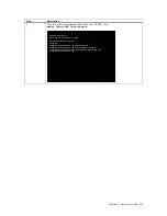
AMI XXX (StorTrends)
Kernel X.X.X-X.XXXXXX on an XXXX

XXXXXXXXXXXXXXX login: root
Password:  
[root@ITXXXXXXXXXXXXX ~]#  mkdir /mnt/source
[root@ITXXXXXXXXXXXXX ~]#  _

Summary of Contents for ManageTrends 2.7

Page 1: ...StorTrends ManageTrends Version 2 7 User s Guide for the StorTrends 1300 Storage Appliance MAN 1300 03 14 08...

Page 2: ...l trademarks and trade names used in this document refer to either the entities claiming the marks and names or their products American Megatrends Inc disclaims any proprietary interest in trademarks...

Page 3: ...ons 2 Cooling Specifications 3 Operating Environment 3 Physical Characteristics 3 StorTrends iTX Software Specifications 3 Volume Replication 3 Advanced Snapshots 3 Backup 3 Networking 3 iSNS Configur...

Page 4: ...izard 29 Step One Advanced Wizard 29 Step Two Create a New Storage Pool 30 Step Three Select Pool 31 Select the Disks 31 Set the RAID Levels 32 Type in your Storage Pool s name 32 Step Four Configure...

Page 5: ...allation 61 Memory Support 61 Figure 5 3 Installing DIMM into Slot 62 Adding PCI Cards 62 PCI Expansion Slots 62 PCI card installation 63 PCI Slot Card Configurations 63 Serverboard Details 64 Figure...

Page 6: ...78 Figure 6 4 Mounting a SATA Drive in a Carrier 78 Installing removing hot swap SATA drives 78 Figure 6 5 Removing a SATA Drive from the Server 79 DVD ROM Drive Installation 79 Power Supply 80 Power...

Page 7: ...ings SNMP Protocol Settings Page 107 Control Panel Network Settings Firewall Settings Page 108 Control Panel Network Settings Firewall Settings Page Modifying 110 Control Panel Network Settings File P...

Page 8: ...59 Storage SAN Snapshot Management 160 Storage Continuous Data Protection CDP 161 Storage Continuous Data Protection CDP Navigating to CDP Management 161 Storage Continuous Data Protection CDP CDP Con...

Page 9: ...Management Create New Replication 191 Storage Resource Management SRM 192 Storage Resource Management SRM 192 Data Collection Analysis and Trending Module 192 Storage Provisioning and Capacity Manage...

Page 10: ...237 Path Information Configuration 237 Errors during Upgrade 237 Appendix E Replication Overview 239 The Business Threat 239 The Solution Remote Replication 239 High Availability with Synchronous Repl...

Page 11: ...263 SAR view Primary Box 263 SAR view Secondary Box 263 SAR Configuring the Schedule 264 SAR Deleting the Schedule 265 Failover Operation 266 Before Failover Operation in Secondary Box 266 After Fail...

Page 12: ...Continuous Data Protection architecture 302 Appendix J WDS and Deduplication in StorTrends iTX 303 The Effects of Packet Loss and Latency on TCP IP Efficiency 303 Figure 1 Effect of TCP protocol on t...

Page 13: ...20 FC SAN 321 FCIP 321 Firewall 321 Frame 321 FTP 321 Gateway 321 Gigabyte 321 Group 322 HA 322 HAK 322 Host 322 HTTP 322 iFCP 323 ILM 323 Internet 323 IP Address 323 IP SAN 323 IPS 324 IPv6 324 IPX 3...

Page 14: ...331 RAID Level 331 Replication 331 Replication Scheduling 331 Router 331 ROW 332 SAFE 332 SAN 332 SAR 333 Schedule 333 SCSI 333 Server 333 Share 333 SLP 333 SMB 334 Snapshot 334 Snapshot Rollback 334...

Page 15: ...ased directly from AMI or from an AMI authorized reseller only If Then You purchased this product from AMI or from a certified AMI reseller Call AMI technical support at 770 246 8645 Please be prepare...

Page 16: ...ends provides this publication as is without warranty of any kind either expressed or implied including but not limited to the implied warranties of merchantability or fitness for a specific purpose S...

Page 17: ...ments Electromagnetic Emissions FCC Class A EN 55022 Class A EN 61000 3 2 3 3 CISPR 22 Class A Electromagnetic EN 55024 CISPR 24 EN 61000 4 2 EN 61000 4 3 EN 61000 4 4 EN 61000 4 5 EN 61000 4 6 EN 610...

Page 18: ...StorTrends 1300 User s Guide StorTrends iTX version 2 7 xviii...

Page 19: ...ormance in mind and includes features for enterprise level storage management such as hardware RAID advanced snapshots volume replication and failover System Features Highlights Transfer block and fil...

Page 20: ...nce Hardware RAID Support Integrated Intel ICH7R Controller 3 Gbps Online capacity expansion RAID level migration Multiple array types per drive Distributed sparing Read with Write back caching Global...

Page 21: ...lication Synchronous Asynchronous Snapshot assisted Journal assisted Replication Wizard Failover Failback One to Many Replication Advanced Snapshots Up to 1 024 read only and 1 024 writeable snapshots...

Page 22: ...2 Maximum of 4 connections per session Multiple levels of authentication Mutual CHAP user name password CHAP authentication and iSCSI initiator WWN name iSCSI Portal Tag configuration from UI View iS...

Page 23: ...apter One Introduction 5 UPS Support Universal UPS Support Supports Windows OS iTX Linux as UPS slaves and many UPS makes and models Applications Supported Oracle SQL Microsoft Exchange VMware and so...

Page 24: ...StorTrends 1300 User s Guide StorTrends iTX version 2 7 6...

Page 25: ...common concepts and terminology Unpack the StorTrends 1300 Storage Appliance You should inspect the box the StorTrends 1300 Storage Appliance was shipped in and note if it was damaged in any way If th...

Page 26: ...ight of the rack resting on them In a single rack installation stabilizers should be attached to the rack In multiple rack installations the racks should be coupled together Always make sure the rack...

Page 27: ...ment nameplate ratings should be used when addressing this concern Reliable Ground A reliable ground must be maintained at all times To ensure this the rack itself should be grounded Particular attent...

Page 28: ...rail to the rear rail of the rack Attach a short bracket to the front side of the right outer rail and a long bracket to the rear side of the right outer rail Adjust both the short and long brackets...

Page 29: ...ons The first is to lock the server into place when installed and pushed fully into the rack which is its normal position Secondly these tabs also lock the server in place when fully extended from the...

Page 30: ...k Do this by lining up the rear of the chassis rails with the front of the rack rails Slide the chassis rails into the rack rails keeping the pressure even on both sides you may have to depress the lo...

Page 31: ...er will extend out the front of the rack Larger chassis should be positioned to balance the weight between the front and the back If a bezel is included on your server remove it Attach the two front b...

Page 32: ...ft the top cover from the chassis to gain full access to the inside of the server To remove the system from the rack completely depress the locking tabs in the chassis rails push the right side tab do...

Page 33: ...Chapter Two Chassis Set Up 15 Accessing the Inside of the System...

Page 34: ...the SATA disk drives Depending upon your system s configuration your system may have one or more drives already installed Step 4 Check the airflow Airflow is provided by three sets of 4 cm fans each s...

Page 35: ...Cable s to both the NIC ports or to just one of them located on the back of the server 4 Connect your keyboard and monitor Plug your keyboard and monitor to the proper ports located on the back of th...

Page 36: ...see the following screen Write down the IP Address listed in the Ip Address field If you have both NICs connected to your network there will be two IP Addresses STOP Once again WRITE DOWN the IP Addr...

Page 37: ...er name itxadmin Default password password Note When you login using the default itxadmin password you have full administrative powers It is advised that once you login you change the password Both th...

Page 38: ...onfiguration allows you to configure the email alerts settings in order to receive notifications on disk failures volume events system and hardware events Note You MUST have an email server setup on y...

Page 39: ...list Information Check this box to trigger an email notification to be sent whenever an informational event is recorded An Information event can be an event such as a system reboot Warning Check this...

Page 40: ...utomatically generated A default NAS Share is also automatically created In the Quick and Easy Setup Wizard the SAN and NAS Volumes are configured to use Exact Provisioning Twenty percent of the physi...

Page 41: ...0 RAID 1 RAID 5 This step will create a Logical disk and a storage pool from all the physical hard disk drives available in the system controller with the RAID type you specify Note Once you select Ne...

Page 42: ...Appliance You are provided with the following options Only SAN Only NAS Both SAN and NAS If you want your Storage Appliance to be used for block level storage only select Only SAN If you want your Sto...

Page 43: ...es cannot exceed the available physical space due to the fact that they are both using Exact Provisioning by default Click Next Note You can use the slider bar to adjust the size of each Volume type I...

Page 44: ...on the values that you have entered Note You can change the default names for volumes and containers at this point Also note that uppercase characters are not allowed in target names Additionally if...

Page 45: ...Chapter Two Chassis Set Up 27 Do not close the window or click anywhere else until the operation completes...

Page 46: ...StorTrends 1300 User s Guide StorTrends iTX version 2 7 28 Step Six All Done No Errors STOP YOU SHOULD NOW BE UP AND RUNNING ALL THE OTHER SECTIONS CAN BE SKIPPED...

Page 47: ...he Advanced Setup Wizard allows you to have more control of the storage being configured Step One Advanced Wizard If the storage has not been configured on your Storage Appliance you will be prompted...

Page 48: ...The screen capture above is from a 3U unit By default the 1U units do not display this screen because the 1U units do not use hardware RAID The 1U units only support RAID 0 RAID 1 RAID 5 and RAID 1n...

Page 49: ...Chapter Two Chassis Set Up 31 Step Three Select Pool Select the Disks Select the Disks that you want to use in your Storage Pool...

Page 50: ...re displayed Keep in mind that your hardware RAID controller may not be fully supported Type in your Storage Pool s name Type in a Storage Pool Name Note The Storage Pool Name must be alphanumeric not...

Page 51: ...s section allows you to configure a SAN Volume and a SAN Target on to the Storage Appliance If you have configured this storage appliance as a NAS Only unit SKIP THIS STEP and go to Step Five Configur...

Page 52: ...Name field enter a name for your SAN Volume The SAN Volume Name must be alphanumeric not have any spaces and be between one and 63 characters in length Enter Volume Size In the Enter Volume Size fiel...

Page 53: ...the actual physical size of the storage device For example if the storage device has an actual physical size of 500 GB the user can assign a size of up to 256 TB per box Based on the consumption of t...

Page 54: ...Target field Enter a name for your Target The Target Name must be alphanumeric not have any spaces and be between one and 63 characters in length Uppercase characters are not allowed in target names N...

Page 55: ...u to configure a NAS Volume and a NAS Share on to the Storage Appliance If you only want to configure this storage appliance as a SAN Only unit SKIP THIS STEP by clicking the Finish button and go to S...

Page 56: ...ion which in the case of the 1U is not typically done because the 1U unit usually ships with all drive bays occupied If you select Thin the volume can be assigned a size greater than the actual physic...

Page 57: ...e at this time otherwise click the Add button and continue on to the next step If you want to create a NAS Share now in the Share Name field enter a unique name for your NAS Share The NAS Share Name m...

Page 58: ...iew and Status When you are finished adding your Volumes click the Finish button A summary will appear Your Storage Appliance will be automatically configured based on the values that you have entered...

Page 59: ...Chapter Two Chassis Set Up 41 Step Seven All Done No Errors STOP YOU SHOULD NOW BE UP AND RUNNING...

Page 60: ...StorTrends 1300 User s Guide StorTrends iTX version 2 7 42...

Page 61: ...three push buttons located on the front of the chassis a reset button a UID button and a power on off button Illustration Name Description UID Button Depressing the UID unit identifier button illumina...

Page 62: ...d also check to make sure that the chassis covers are installed Finally verify that the heatsinks are installed properly This LED will remain flashing or on as long as the indicated condition exists S...

Page 63: ...ont of the SAS drive carrier indicates drive activity A connection to the backplane enables this LED to blink on and off when that particular drive is being accessed Red The SES2 compliant backplane a...

Page 64: ...StorTrends 1300 User s Guide StorTrends iTX version 2 7 46...

Page 65: ...electrical equipment This is to avoid making a complete circuit which will cause electrical shock Use extreme caution when using metal tools which can easily damage any electrical components or circu...

Page 66: ...that have been removed away from the system or on a table so that they won t accidentally be stepped on While working on the system do not wear loose clothing such as neckties and unbuttoned shirt sle...

Page 67: ...or PCBs come into contact with your clothing which may retain a charge even if you are wearing a wrist strap Handle a board by its edges only do not touch its components peripheral chips memory modul...

Page 68: ...ts 4 Disconnect all the cables and label the cables for easy identification 5 Use a grounded wrist strap designed to prevent static discharge when handling components Removing the Chassis Cover After...

Page 69: ...ard towards the front of the chassis until it snaps into place Before Installing the Chassis into a Rack 1 Make sure that the rack is securely anchored onto an unmovable surface or structure before in...

Page 70: ...StorTrends 1300 User s Guide StorTrends iTX version 2 7 52...

Page 71: ...d weight of the server board can cause it to bend if handled improperly which may result in damage To prevent the server board from bending keep one hand under the center of the board to support it wh...

Page 72: ...of the CPU pins are bent otherwise contact the retailer immediately Do NOT touch the processor contacts AMI recommends that you leave the protective cover on the processor until it is ready to be inst...

Page 73: ...ket protection cover from the Load Plate Leave the Load Plate in its fully open position 5 Visually inspect the socket for bent Socket pin contacts If there are bent Socket pin contacts stop here Cont...

Page 74: ...ce 8 Verify that processor is within the Socket and properly mated to the orientation keys 9 Rotate the Load Plate to its fully closed position IN T E L C O R P O R A T IO N A T LA N TA G A A M E R IC...

Page 75: ...alling the heatsink for the first time You must use thermal paste on previously installed heatsinks and heatsinks without pre applied TIM Installing the Heatsink Step Action 1 Place the heatsink on to...

Page 76: ...age done to the CPU or the CPU socket Step Action 1 Unscrew and remove the heatsink screws from the server board 2 Hold the heatsink and gently wriggle the heatsink to loosen it from the CPU Do not us...

Page 77: ...ector locations DVD ROM Drive cable IDE 1 Control Panel cable JF1 SATA cables SATA0 SATA3 SGPIO cable SGPIO1 to SATA backplane Connecting Power Cables The server board has a 20 pin primary power suppl...

Page 78: ...1300 User s Guide StorTrends iTX version 2 7 60 Figure 5 1 Front Control Panel Header Pins JF1 I O Ports The I O ports are color coded in conformance with the PC 99 specification Figure 5 2 Rear Panel...

Page 79: ...press down on the DIMM module until it snaps into place in the slot Repeat for all modules Memory Support The SERVERBOARD supports up to 8 GB of unbuffered ECC non ECC DDR2 667 533 400 SDRAM Interlea...

Page 80: ...ng PCI Cards PCI Expansion Slots Two riser cards are used to support add on cards to the system The StorTrends 1300 chassis can accommodate one standard size full height full length and one low profil...

Page 81: ...ab that corresponds to the slot you wish to populate Insert the expansion card into the correct riser card pushing down with your thumbs evenly on both sides of the card PCI Slot Card Configurations L...

Page 82: ...purposes only LAN2 LAN1 VGA COM1 USB0 1 Kb Mouse SEPC SBX2 SBX1 Speaker BIOS SIMSO ATI ES1000 ICH7R South Bridge Intel 3010 North Bridge COM2 Floppy USB4 5 USB2 3 SATA0 SATA1 SATA2 SATA3 JPW1 JPW2 LG...

Page 83: ...assis Intrusion Header JLED Power LED Header JPW1 24 Pin ATX Power Connector JPW2 8 pin Power Connector Required JWOR Wake On Ring header LAN1 LAN2 Ethernet RJ45 Gigabit LAN Ports PW3 Power Supply Fai...

Page 84: ...V 9 5VS5B 22 5V 10 12V 23 5V 11 12V 24 COM 12 3 3V Processor Power Connector JPW2 must also be connected to the power supply to provide power for the processor s Processor Power Pin Definitions JPW2 P...

Page 85: ...located on pins 9 and 10 of JF1 Attach the NIC2 LED cable to display network activity Refer to the table on the right for pin definitions NIC1 LED Pin Definitions JF1 Pin Definitions 9 VCC 10 Ground...

Page 86: ...d Power Button The Power Button connection is located on pins 1 and 2 of JF1 Momentarily contacting both pins will power on off the system This button can also be configured to function as a suspend b...

Page 87: ...NC indicates no connection Serial Port Pin Definitions COM1 COM2 Pin Definition Pin Definition 1 DCD 6 DSR 2 RXD 7 RTS 3 TXD 8 CTS 4 DTR 9 RI 5 Ground 10 NC Fan Headers The server board has six fan he...

Page 88: ...al speaker place the speaker cable header on all four pins Speaker Connector Pin Definitions J9 Pin Definition Pins 3 4 Internal Speaker Pins 1 4 External Speaker ATX PS 2 Keyboard and PS 2 Mouse Port...

Page 89: ...upply Fail Connect a cable from your power supply to the Power Supply Fail header PW3 to provide a warning of power supply failure This warning signal is passed through the PWR_LED pin to indicate a p...

Page 90: ...een two pins to change the function of the connector Pin 1 is identified with a square solder pad on the printed circuit board Refer to the server board layout page for jumper locations Note On two pi...

Page 91: ...Disable Jumper JPF allows you to enable or disable the Power Force On function If enabled the power will always stay on automatically If this function is disabled the normal setting the user needs to...

Page 92: ...lly designates the location of pin 1 A single floppy disk drive ribbon cable has 34 wires and two connectors to provide for two floppy disk drives The connector with twisted wires always connects to d...

Page 93: ...t damage to any printed circuit boards PCBs it is important to handle them very carefully The following measures are generally sufficient to protect your equipment from ESD damage Precautions Use a gr...

Page 94: ...out of the airflow path The control panel LEDs inform you of system status System Fans Three 4 cm heavy duty counter rotating fans provide the cooling for the StorTrends 1300 Each fan unit is actually...

Page 95: ...the power to the system first remove the chassis cover and unplug the fan cable from the server board Unscrew the failed blower fan from the chassis and pull it completely out from the server board I...

Page 96: ...rive in a Carrier Use caution when working around the SATA backplane Do not touch the backplane with any metal objects and make sure no ribbon cables touch the backplane or obstruct the holes which ai...

Page 97: ...e the top cover and at the same time push the cover away from you until it stops You can then lift the top cover from the chassis to gain full access to the inside of the server With the chassis cover...

Page 98: ...ty meaning you can replace the failed module without powering down the system Removing Replacing the Power Supply You do not need to shut down the system to replace a power supply module The redundant...

Page 99: ...straight out with the handle provided The power supply wiring was designed to detach automatically when the module is pulled from the chassis Installing a new power supply Replace the failed power su...

Page 100: ...StorTrends 1300 User s Guide StorTrends iTX version 2 7 82...

Page 101: ...erview This section describes how to manage the Storage Appliance Connecting to the Storage Appliance from another system Type the IP Address of the Storage Appliance into your Internet Browser Micros...

Page 102: ...and password before you can gain access to it Enter your username and password Default user name itxadmin Default password password Note When you login using the default itxadmin password you have ful...

Page 103: ...on relevant to the hardware health of your ManageTrends box Here you can view the current status of the system s fans temperatures and server board voltages Event entries for example alerts via emails...

Page 104: ...rends stack is a very powerful SRM module that takes care of Trending Analysis and Reporting ManageTrends provides a very insightful console to understand and analyze what is happening behind the scen...

Page 105: ...export the event log as an XML file so that you can import it in any XML aware application For example Microsoft Office Excel program Save as Text button This button allows you to export the event lo...

Page 106: ...StorTrends 1300 User s Guide StorTrends iTX version 2 7 88 Control Panel...

Page 107: ...e Storage Appliance and of many of its individual components Date and Time The Date and Time Settings page displays the Time Zone Server Date Server Time NTP Configuration and NTP server information T...

Page 108: ...ersion Number Build Date Manufacturer System Uptime System Date and System Time information This page also lists the IP and MAC Addresses always 2 minimum of the Storage Appliance Control Panel System...

Page 109: ...TP Server Type your network s NTP server s FQDN or IP address into this field Synchronize with Local System button Use this button to set the Storage Appliance s time to be the same as that of the sys...

Page 110: ...d Password Field Item Description FTP Address Type your FTP server name or IP address into this field Path Type the upgrade path in this field For example upgrade User Name Type the user name for the...

Page 111: ...nel System Information Icon System Control Page This page allows you to shutdown or reboot your Storage Appliance Select the appropriate button You also have the option to allow the Storage Appliance...

Page 112: ...o select the mode for the system that you are connecting to the UPS For example the Master system is the system that is connected directly to the UPS via serial cable or USB cable Only the Master can...

Page 113: ...Chapter Seven Managing the Storage Appliance 95 Control Panel Themes Allows you to use different color configurations for the GUI Control Panel Themes Red Control Panel Themes Olive Green...

Page 114: ...StorTrends 1300 User s Guide StorTrends iTX version 2 7 96 Control Panel Themes Blue Note You must clear the cache on your Internet browser in order to see the new theme...

Page 115: ...nterface Default Gateway Primary DNS Server Secondary DNS Server and the DNS Suffix This page also allows you to select between Obtaining IP and DNS Addresses automatically or specifying a specific IP...

Page 116: ...twork card is displayed for the selected NIC A Media Access Control address MAC address is a unique identifier attached to most network adapters NICs Maximum Transmission Unit MTU This field displays...

Page 117: ...e Ethernet controller is in half duplex mode Bad Packets Received This field reports the number of bad packets received In other words a bad frame that was marked as an error by PHY Control Panel Netw...

Page 118: ...on or storage CRCs are popular because they are simple to implement in binary hardware are easy to analyze mathematically and are particularly good at detecting common errors caused by noise in transm...

Page 119: ...rier sense signal during every transmission Failure to do so may indicate that the link has failed or that the PHY has an incorrect link configuration This register only increments if transmits are en...

Page 120: ...e Team button You can also delete teamed NICs by clicking on the Delete Team button Once you are satisfied with your settings you can click the Apply button You can also revert back to your original s...

Page 121: ...a DHCP server Specify IP Address and DNS Server Addresses To specify an IP Address Subnet Mask Gateway and DNS information left click the Specify an IP address and DNS server address option The defau...

Page 122: ...obtain an IP Address and DNS server address from a DHCP server Specify IP Address and DNS Server Addresses To specify an IP Address Subnet Mask Gateway and DNS information left click the Specify an I...

Page 123: ...he subnet mask you want the network interface card to use Default Gateway Type the IP address of the gateway you want the network interface card to use Press the ENTER key to continue This field must...

Page 124: ...gs Page Create Teaming Balance Round Robin This option transmits packets in sequential order from the first available slave NIC in the team through the last This mode provides load balancing and fault...

Page 125: ...gents implement the various system related MIBs They also implement the AMI ManageTrends software MIB For all supported MIBs an agent can send information to the SNMP requester To send SNMP traps the...

Page 126: ...ubnet you want to either block or always allow Subnet Mask This field allows you to enter the specific subnet of the IP address range that you want to use Protocol This drop down box allows you select...

Page 127: ...you select the ICMP UDP or TCP protocols The Storage Appliance can be configured to accept or ignore packets based on specified type Start Port This field allows you to enter the first port of the por...

Page 128: ...ol Panel Network Settings Firewall Settings Page Modifying You can edit any of the IP address ranges by selecting the IP address range from the main Firewall window You can enter your adjustments and...

Page 129: ...s programs to make requests for files and services on remote systems running Microsoft Windows operating systems on the Internet Note If you navigate away from the Set Windows File Protocol page or it...

Page 130: ...ange the settings you must disable CIFS first To disable the Windows File Server Protocol CIFS left click the Disable button Enable Windows File Server Protocol CIFS Complete all the fields and then t...

Page 131: ...y the IP addresses listed to access the Storage Appliance Allow Following IP Addresses Only field This field contains the list of the IP addresses that have access to the Storage Appliance shares and...

Page 132: ...rk Settings File Protocols Settings Page Set Apple File Protocol Page To access the Set Apple File Protocol page click the Apple link Field Item Description Enable Apple File Protocol AFP Left click t...

Page 133: ...lick the HTTP FTP link Field Item Description Enable HTTP Sharing Left click this box to enable HTTP sharing Enable Secure HTTP Sharing Left click this box to enable secured HTTP sharing Note If you e...

Page 134: ...s The Groups List page displays the Total Number of Groups the Group Name Group ID and the Type This page allows you to Create New groups and Remove groups This page also allows you to change Group Pr...

Page 135: ...ew and edit the properties of a user For example you can change the password and or change the Full Name of the user You will not be able to change the User Name Login Name To change the User Name cre...

Page 136: ...tricted Users and Administrators Any users that belong to either group will automatically be granted rights associated with that group Note Local access basically means access to the Storage Appliance...

Page 137: ...ance 119 Removing a User To delete a user highlight their name and click the Remove button After you confirm that you really want to remove the user the list will refresh and a message will appear sta...

Page 138: ...ead only permissions to manage the system The users that belong to the Administrator group have full access to manage the system Field Item Description Group Name field This field lists the groups Cre...

Page 139: ...t of the Group There are two default local access groups to the StorTrends UI pages Restricted Users and Administrators Any users that belong to either group will automatically be granted rights assoc...

Page 140: ...on 2 7 122 Removing a Group To delete a Group highlight the Group Name and click the Remove button After you confirm that you really want to remove the Group the list will refresh and a message will a...

Page 141: ...allows organizations to centrally manage and share information on network resources and users while acting as the central authority for network security In addition to providing comprehensive directo...

Page 142: ...orkgroup or Domain Name into this field Select whether it is a WorkGroup WINNT Domain or Active Directory from the dropdown menu Note The pre windows 2000 domain name is an optional field Organization...

Page 143: ...NIS uses the client server model and the Remote Procedure Call RPC interface for communication between hosts NIS consists of a server a library of client programs and some administrative tools NIS is...

Page 144: ...Multiple ISNS servers Portals The iSCSI Portal Settings page allows you to Enable iSCSI Service and the Portal s This page also displays the Target Base Name Port Address Portal Tag and Status Statist...

Page 145: ...nter the IP address of an ISNS server that you want to add to the ISNS server IP list thereby registering the StorTrends iTX server appliance with that server Add button Use this button to add an ente...

Page 146: ...or using the TCP IP protocol and the iSCSI protocol An iqn name uses the following format Type Date Organization Naming Authority Subgroup Naming Authority iqn 1991 10 com ami target Note This is not...

Page 147: ...ou to adjust the Maximum Outstanding R2T value in seconds This field can have a value of 1 through 65535 The default value is 0 seconds Default T2W This field allows you to adjust the default T2W valu...

Page 148: ...ontains sent and received statistical information for SCSI payload iSCSI PDUs and iSCSI PDU bytes Error Statistics This list contains count statistical information for failed login attempts failed ses...

Page 149: ...f the listed sessions Terminate button Use this button to terminate a selected session Note Initiators will try automatically to reconnect to targets after the sessions are terminated If the terminati...

Page 150: ...d initiators that can be accessed by the Storage Appliance Note Most ISNS servers will not allow the initiator list to be queried without registering one target node with it first This can be done by...

Page 151: ...ert settings Icon Description SNMP Traps The SNMP Alert Settings page allows you to Enable SNMP Alert Notifications This page also allows you to input the Community Name Target IP This page allows you...

Page 152: ...n allows you to delete a selected item from the list Information box Check this box to trigger an SNMP alert notification to be sent whenever an informational event is recorded An Information event ca...

Page 153: ...eft click this button to add an Email address Delete button This button allows you to delete a selected item from the list Information Check this box to trigger an email notification to be sent whenev...

Page 154: ...ds 1300 User s Guide StorTrends iTX version 2 7 136 Control Panel License Settings Icon Description Update License The License Information page allows you to view update the license for the Storage Ap...

Page 155: ...e required any time you make changes or upgrades to the licensing of your product Note Your Service Key is required in order for your License Key to be generated Each StorTrends Service Key is generat...

Page 156: ...ows you to configure RAID arrays using Software RAID or supported H W RAID controllers Physical Disks Management The Physical Disks Management page displays all physical disks attached to the RAID con...

Page 157: ...al disk The physical disk status can be in any of the following states None The physical disk state was not found Online The physical disk is part of an active Logical Disk RAID Array Ready The physic...

Page 158: ...field displays the manufacturer of the physical disk Model This field displays the model number of the physical disk Serial Number This field displays the serial number of the physical disk Firmware V...

Page 159: ...owing states Initializing The Logical Disk is being initialized Online The Logical Disk is online and ready to use Degraded This means that one or more disks have failed but the LD still can be used T...

Page 160: ...tus of the physical disk The physical disk status can be in any of the following states Initializing The Logical Disk is being initialized Online The Logical Disk is online and ready to use Degraded T...

Page 161: ...isks Involved This field displays all the physical disks involved in this Logical Disk The physical Port location of the physical disk on the Controller and on which Controller it is attached to is di...

Page 162: ...e This field displays the name of the Logical Device name Status This field displays the status of the logical disk The disk can be in any of the following states Initializing The Logical Disk is bein...

Page 163: ...ows the current size of the array and allows you to specify the expanded capacity of the Logical Disk Spare type This field displays the spare configuration for this LD Select Disks This field allows...

Page 164: ...can consist of the following a server with a network interface card s or Host Bus Adapter HBA with iSCSI over TCP IP capability such as a server running Microsoft 2003 Server and iSNS server a storage...

Page 165: ...esired 11 Enable File Protocols 12 Schedule Snapshots optional Step 1 Create a Logical Disk A Logical Disk is a RAID array Step Action 1 Make sure that you are logged into the Storage Appliance Click...

Page 166: ...used or is unavailable Step Action 1 Make sure that you are logged into the Storage Appliance and have already created a Storage Pool Expand the Pool node located in the storage tree menu 2 Click on...

Page 167: ...nt link to go back to the Volume Management page Step 5 Enable the Port of the Target on the Storage Appliance Step Action 1 Make sure that you are logged into the Storage Appliance and have already a...

Page 168: ...your iSCSI Initiator You must follow the instructions for your specific iSCSI initiator if yours differs from the iSCSI Initiator used in this example Step Description 1 From the application server op...

Page 169: ...t does not appear in the list try the following Check to verify that you added the iSNS server in the iSNS Servers tab This is necessary if you are using the iSNS Zoning security feature on your Stora...

Page 170: ...d If you are using a different initiator list of supported initiators is available from AMI then the procedure will differ according to that particular software hardware s specifications The procedure...

Page 171: ...nt on the server Step Description 1 Open Disk Management from the Computer Management utility in your Microsoft Windows operating system hosting your initiator software 2 The Target is listed as one o...

Page 172: ...age device For example if the storage device has an actual physical size of 500 GB the user can assign a virtual size of up to 256 TB Based on the consumption of the storage device s physical capacity...

Page 173: ...escription of the NAS Share in the Description field This step is optional 6 In the Folder Path field type in the path you want to share You can also Browse to the desired Volume or Folder 7 Simply ch...

Page 174: ...l need to be formatted and assigned a drive letter in Disk Management Step Action 1 Make sure that you are logged into the Storage Appliance and have already created a SAN or NAS Volume Expand the Vol...

Page 175: ...adding one or more existing Logical Disks to it Logical Disks Involved Name This field displays the name of the Storage Pool Capacity This field displays the size of the Storage Pool RAID Level This...

Page 176: ...snapshot Failed The SAN Volume has failed Chunk Size This field displays the chunk size of the SAN Volume Capacity This field displays the capacity of the SAN Volume Volume Type This field displays t...

Page 177: ...tion Click on Continuous Data Technology link at the top of the page 3 Select the Volumes or Consistency Groups that you want to recover You can select multiple Volumes or Consistency Groups 4 Click t...

Page 178: ...s to be stopped Create Snapshot button Select this button to create a snapshot Schedule Snapshots Opens the Snapshot Scheduling page Delete button Select this button to delete a snapshot Delete All bu...

Page 179: ...ay to consistently review and recover volumes of a Consistency group For SAN volume volume groups that are not enabled for Journaling the UI provides a mechanism to group them logically during a revie...

Page 180: ...rtains only to the currently selected container If you want to perform a CDP on a different CG Volume you need to go back and select the corresponding container Storage Continuous Data Protection CDP...

Page 181: ...iate event to review and restore It also gives a feel of the time by indicating the time of the day picturesquely Most importantly it allows the user to freely review both in the forward and backward...

Page 182: ...an also be specified in this panel Storage Continuous Data Protection CDP Time Step Control Panel The time step needed to precisely move the slider is controlled by the Time Step Control Panel The dia...

Page 183: ...tection CDP Snapshot based sliding This screen shows an example of using the Snapshot Control Pressing the left and right button moves the slider from one snapshot to another Storage Continuous Data P...

Page 184: ...Flashback window The CDP utility makes a note of three different types of events taking place in the system a Snapshots b Application events and c Windows events Application events are modifications...

Page 185: ...eft hand corner of the window After choosing the recovery time or event click on Review to start the review process This can also be done from the Event View The Progress bar starts blinking and stops...

Page 186: ...perform a consistency check to make sure that this is the image you wish to rollback Once you are satisfied logout of the target and perform a rollback operation If you are not satisfied logout and ch...

Page 187: ...ated within the given time frame Storage Continuous Data Protection CDP Scrolling Snapshots Each flying window represents a consistent snap group taken across all the volumes of the CG For a SAN CG th...

Page 188: ...Connect your application server Microsoft Exchange SQL and so on to this image and perform a consistency check to make sure that this is the image you wish to rollback Once you are satisfied logout of...

Page 189: ...splays the chunk size of the NAS Volume Volume Type This field displays the type of the NAS Volume The default is Redirect on Write ROW Provision Type This field displays the provisioning type being u...

Page 190: ...a list of users and groups that you can set individual permissions for Select the users or groups that you want to assign specific permissions for Add them to the Permission List box 3 From the Permi...

Page 191: ...field displays the name of the Target Status This field displays the status as either Enabled or Disabled You can use the button to toggle it from Enabled or Disabled Disable Click on this button to...

Page 192: ...ilable Replication Types Replication Type Physical Location of the Secondary Box Volume Supported Synchronous Local and Remote SAN Volumes only Snap Assisted Replication Remote Both NAS and SAN Volume...

Page 193: ...Chapter Seven Managing the Storage Appliance 175 Synchronous Local SAN Volume Replication This illustration shows replication taking place on the same box...

Page 194: ...StorTrends 1300 User s Guide StorTrends iTX version 2 7 176 Synchronous SAN Volume Replication using a Remote Box This illustration shows volume replication using two separate boxes...

Page 195: ...how to create a new Synchronous Replication Pair using the Create Replication Wizard Step Action 1 Navigate to the Replication link in the tree menu 2 The Create Replication Wizard opens 3 Select the...

Page 196: ...replication onto a Secondary Volume located on the same box and Secondary box Select the SAN Volumes that you want to replicate You can configure multiple replication pairs here Select the Secondary...

Page 197: ...ation node in the navigation tree Field Description Existing Replication Pairs Table This table lists all existing replication pairs along with their information such as Local Volume Remote Volume Rem...

Page 198: ...straight forward This allows you to delete a replication pair After it is deleted the Volumes are considered separate Volumes The Volumes will not be deleted Update By clicking Update you can update t...

Page 199: ...eate a new Snap Assisted Replication SAR Pair using the Create Replication Wizard Note You must have Snapshots scheduled for the Volumes that are involved in the SAR pair before Snap Assisted Replicat...

Page 200: ...want to replicate You can configure multiple replication pairs here Select the Secondary Volume location from the drop down menu associated with the Volume that you have selected If no Volume is confi...

Page 201: ...ported in this release Click the Next button to continue 11 The Configure the Replication specific parameters page opens Type the name you want to use for your Consistency group in the Consistency gro...

Page 202: ...d displays the SAN Volumes size must be the same for both volumes in a pair Replication Role This field displays the Replication Role The Storage Appliance volume can either be the Primary or the Seco...

Page 203: ...ght forward This allows you to delete a replication pair After it is deleted the Volumes are considered separate Volumes The Volumes will not be deleted Update By clicking Update you can update the Re...

Page 204: ...o be grouped as highly available cluster nodes for Microsoft initiators This together with MPIO DSM for StorTrends will allow deploying solutions with extreme fault tolerance and total availability Th...

Page 205: ...on link in the tree menu 2 The Create Replication Wizard opens 3 Select the IP Address of the Primary box The Primary box is the where the Volume that you want to replicate is located 4 Select High Av...

Page 206: ...ss this page click on the Replication node in the navigation tree then click High Availability Field Description Local Remote Pool This field displays the pair s Local and Remote Storage Pools respect...

Page 207: ...ght forward This allows you to delete a replication pair After it is deleted the Volumes are considered separate Volumes The Volumes will not be deleted Update By clicking Update you can update the Re...

Page 208: ...tion pair can be synchronized manually Resync Priority This field allows you to customize your resync priority 25 is the default setting Resync is used to synchronize the volumes Setting the resync pr...

Page 209: ...ppliance or select it from the remote server dropdown menu 5 Enter credentials for the remote Storage Appliance and click on Next Once logged in all suitable SAN Volumes on the remote Storage Applianc...

Page 210: ...utilization 4 Performance monitoring and characterization 5 Backup and Recovery management 6 Workflow management 7 ILM 8 CSM 9 Intuitive Presentation and reporting mechanisms Data Collection Analysis...

Page 211: ...of what is present today and predicting how much of growth is anticipated over the next few months year or even beyond Just current inventory which most of the storage stacks provide is simply not en...

Page 212: ...total I O activity going on at the moment The I O sizes chosen are 512 byte 4K 8K and 64K reads or writes I O latency monitoring and analysis Today with so many SATA drives populating a single 2U or 3...

Page 213: ...s snapshots are being created for backup and recovery StorTrends with Tiered Storage and three level space mapping ensures that snapshots are maintained in the most capacity optimized manner The next...

Page 214: ...e are various products in the market today that do this job online with the incoming stream of data or offline with data at rest Though the need is felt the technology of Data Classification is still...

Page 215: ...een a Logical Drive a Container and a Tier StorTrends Tiered Storage and ILM Scaling across tiers StorTrends even at the block level handles information and not just data Data when it is assigned a ri...

Page 216: ...arious degrees of importance The relevance of emails and corresponding references to them sharply tapers off with the passage of time StorTrends has a powerful Data Collection and Trending agent that...

Page 217: ...ectronic record Keeping Sarbanes Oxley SEC 17a 3 4 Texas Public Information Act How StorTrends Tiered Storage and ILM Works At the core of StorTrends iTX stack is a data collection and trending module...

Page 218: ...that data blocks are migrated without corruption in the fastest possible time In essence even at the block level efficient ILM is implemented by maintaining the block level metadata No content analysi...

Page 219: ...he RAID card in the number of disk that can be added to one LD maximum expansion support per LD Some RAID cards may have restrictions on creating arrays across enclosures If a storage system contains...

Page 220: ...nning above it The method of predicting the I O load on the system at given point in time is done by the workflow analysis How should the data be re striped The data should be re striped in the manner...

Page 221: ...ied and is also extrapolated dotted line to show the predicted growth The bottom line is the space occupied by the file system this is applicable for NAS Volumes only In the above figure you can see t...

Page 222: ...performance and the blue colored line in the chart indicated the write performance This chart has a sliding window that can be dragged and adjusted for viewing detailed information for a particular pe...

Page 223: ...ce The IO Performance chart displays the IO performance of the volume selected In the chart above the volume is undergoing more 64 K read and writes compared to other segments For instantaneous perfor...

Page 224: ...time that an I O takes to complete once it has been dispatched to the LD and is measured in microseconds This value should be as low as possible Each line in the graph is indicative of the behavior o...

Page 225: ...Appliance 207 System Performance System performance is tracked in the form of instantaneous CPU and Memory Utilization These values are also polled on a 5 second interval Above is the graph showing t...

Page 226: ...rTrends iTX version 2 7 208 System performance is tracked in the form of instantaneous CPU and Memory Utilization These values are also polled on a 5 second interval Above is the graph showing the Mem...

Page 227: ...rs The chart above shows the Random Access patterns of data The ideal situation would be for the most frequently accessed data red be present in the high cost tier yellow background and least accessed...

Page 228: ...210 Container Space Management The above charts show how a container was before expansion and below how it is after expansion and re striping The x axis represents the Logical Drives and the y axis r...

Page 229: ...n be prevented by regenerating missing data from the remaining data and parity information stored on other hard disk drives in the volume RAID Benefits RAID has gained popularity because it improves I...

Page 230: ...8 KB to 512 KB For example in a four hard disk drive system using only disk striping as in RAID level 0 segment one is written to hard disk drive one segment two is written to hard disk drive two and...

Page 231: ...Since the contents of the hard disk drive are completely written to a second hard disk drive it does not matter if one of the hard disk drives fails Both hard disk drives contain the same data at all...

Page 232: ...in the StorTrends iTX Storage Appliance the capacity of the hard disk drives in the StorTrends iTX Storage Appliance the need for data redundancy the hard disk drive performance requirements The facto...

Page 233: ...Description uses RAID 0 provides high data throughput especially for large files Any environment that does not require fault tolerance strong points Provides increased data throughput for large files...

Page 234: ...to create an array type Point Description uses Use RAID 1n for small databases or any other environment that requires the best fault tolerance level but small capacity strong points RAID 1n provides c...

Page 235: ...for large files Use RAID 5 for transaction processing applications because each hard disk drive can read and write independently If a hard disk drive fails the StorTrends iTX Software uses the parity...

Page 236: ...StorTrends 1300 User s Guide StorTrends iTX version 2 7 218...

Page 237: ...e host device 2 Configure at least one local user make sure password is 12 characters long min and a Volume with iSCSI support Create a LUN and assign to a Target Enable that Target 3 In Security page...

Page 238: ...o Up to date 6 Click on Authentication icon in Control panel and then on Rescan list button as necessary to see the name of the Initiator on the list 7 Select that Initiator and then enter and confirm...

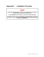
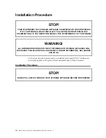
Page 239: ...TALL THE STORTRENDS ITX SOFTWARE ON THE STORTRENDS 1300 STORAGE APPLIANCE ONLY IT IS RECOMMENDED THAT YOU INSTALL AT LEAST TWO HARD DISK DRIVES YOU MUST PHYSICALLY ATTACH AN EXTERNAL USB CD ROM DRIVE...

Page 240: ...STALL THE STORTRENDS ITX 2 7 SOFTWARE WARNING ALL INFORMATION STORED ON THE STORTRENDS ITX STORAGE APPLIANCE WILL BE ERASED THIS INCLUDES ALL USER RIGHTS TARGET INFORMATION NAS SHARES AND SO ON Use th...

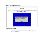
Page 241: ...LED AN EXTRA NIC YOU MUST REMOVE IT BEFORE PROCEEDING WITH THE INSTALLATION Attach a Keyboard and Monitor Attach a keyboard and monitor to your StorTrends Storage Appliance Power on your StorTrends iT...

Page 242: ...pliance 2 You should see the Welcome to AMI StorTrends ITX screen If not you have to reset the power on your StorTrends 1300 storage appliance and start over Press the ENTER to continue American Megat...

Page 243: ...cally detect them and will mirror the installation of itself over both hard disk drives Prior to beginning the installation you will be prompted with the following message Detected multiple disks The...

Page 244: ...n where it tells you that the installation is complete Press the ENTER key to reboot 8 Congratulations You have successfully installed StorTrends iTX on your StorTrends 1300 storage appliance At this...

Page 245: ...e STOP Currently Upgrading from all versions of StorTrends other than StorTrends 2 7 XXXX is not supported WARNING BACK UP YOUR DATA BEFORE PROCEEDING StorTrends iTX X X Upgrade Current StorTrends ITX...

Page 246: ...through your Internet browser and check the event log for the Storage Appliance It should report Upgrade Success FTP Upgrade Procedure Using ManageTrends STOP The FTP Upgrade Procedure is not support...

Page 247: ...quires that you be in front of the actual Storage Appliance that you are attempting to upgrade Attach a Keyboard and Monitor Attach a keyboard and monitor to your StorTrends 1300 storage appliance Pow...

Page 248: ...e Interface press the ALT F2 keyboard combination AMI StorTrends Console Interface System Info Host Name ITXXXXXXXXXXXXX Ip Address XXX XXX XXX XXX XXX XXX XXX XXX System Date MM DD YYYY System Time H...

Page 249: ...TER key Next type in your password and press the ENTER key The default password is password If you changed your admin password use the admin password Also while you type the password in the cursor wil...

Page 250: ...XXXXXXX _ 5 At the prompt type the following command followed by the ENTER key mkdir mnt source AMI XXX StorTrends Kernel X X X X XXXXXX on an XXXX XXXXXXXXXXXXXXX login root Password root ITXXXXXXXXX...

Page 251: ...NTER key mount dev scd0 mnt source AMI XXX StorTrends Kernel X X X X XXXXXX on an XXXX XXXXXXXXXXXXXXX login root Password root ITXXXXXXXXXXXXX mkdir mnt source root ITXXXXXXXXXXXXX mount dev scd0 mnt...

Page 252: ...UPGRADE directory 8 The StorTrends Upgrade console interface will appear Press the ENTER key to proceed AMI XXX StorTrends Kernel X X X X XXXXXX on an XXXX XXXXXXXXXXXXXXX login root Password root ITX...

Page 253: ...ck up before proceeding Press the ENTER key to proceed or escape out to backup first 10 The upgrade process will begin You will be able to view its progress StorTrends iTX X X Upgrade As a precautiona...

Page 254: ...the prompt type the following commands followed by the ENTER key umount mnt source reboot The Storage Appliance will reboot StorTrends iTX X X Upgrade Upgrade to X X is successful Reboot the machine...

Page 255: ...Enable FTP access on that Share Also verify that the Storage Appliance has been configured for FTP access Control Panel Network Settings File Protocols HTTP FTP 4 Copy the upgrade file into this Shar...

Page 256: ...StorTrends 1300 User s Guide StorTrends iTX version 2 7 238...

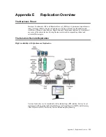
Page 257: ...nsolidation Regulation and Compliance imposed by Government are some of the major factors driving Businesses towards incorporating robust and reliable DR strategies The Solution Remote Replication Hig...

Page 258: ...ce is a challenge for Synchronous Replication Beyond tens of miles the delays and latencies incurred renders the solution impractical Asynchronous Replication This is the most preferred and feasible a...

Page 259: ...errors like viruses and accidental erasures are not handled by synchronous replication Due to inline nature of Synchronous Replication latency plays a very big factor in its viability Traditional Copy...

Page 260: ...synchronous replication Based on Redirect On Write ROW this stack provides Near CDP snapshots Here storage capacity is provisioned via a very space efficient three level capacity allocation map which...

Page 261: ...dwidth Unlike most of the present day Storage servers StorTrends offer intuitive wizards to assist in Fail over fail back and rollback in the event of a disaster Delta snaps In Snap assisted replicati...

Page 262: ...replicated it will be overwritten with the new configuration from the primary system This temporary share configuration will be merged with the original configuration during a Failover The User datab...

Page 263: ...rnaling module to Implement Zero Memory Copy transactions and coexist with other replication agencies e g Synchronous Replication Residing at the very core of the I O stack this module forms the nucle...

Page 264: ...nal file failure Volume Rollback etc which also cause this transition Eventually over time when the Journal catches up again a reverse transition brings it back to JAR Elaborate instrumentations are p...

Page 265: ...on high availability pair using the replication wizard Step Action 1 The first step involves logging in to the primary node s ManageTrends and going to the replication tab It is assumed here that the...

Page 266: ...have been pre created and the targets added and enabled It is also possible to create a new volume and targets for secondary with the wizard The following screen shows selection of replication pairs t...

Page 267: ...Replication Overview 249 Step Action 3 If a new volume creation option has been selected the new container and new volume have to be configured Creation of Remote Container Creation of Remote Volume...

Page 268: ...by one Please allow a few seconds for the replication pairs to be created and the screen to refresh itself with the replication pairs CLI Command for Creating a Synchronous Replication Pair A sample...

Page 269: ...Appendix E Replication Overview 251 Synchronous Replication and High Availability Pair Details Synchronous Replication Details High Availability Pair Details...

Page 270: ...n pair is done by clicking on the delete button in the primary node This button is disabled by default in the secondary node In case the replication pair has become disconnected and there is a need to...

Page 271: ...tatus Split operation is performed from the primary node using the split button in ManageTrends on CLI command The following screenshot shows the result of a split operation The connection mode Manual...

Page 272: ...host name IP 172 16 70 77 Remote target name iqn 1991 10 com ami itx0030488422eedaa8 mtarget Remote initiator name iqn 1997 05 com cisco 01 30488422ee Success root ITX0030488657ee cli list c StoragePo...

Page 273: ...lication resumes and the out of sync percentage starts going down till it becomes fully in sync and out of sync percentage becomes zero Join Replication and Resync Progress CLI Command for Joining Syn...

Page 274: ...one by clicking on the failover button in the original secondary node Once the failover completes the replication role in the original secondary becomes primary Synchronous Replication Failover Before...

Page 275: ...hown below root ITX0030488422ee cli perform t failover l Storage1_SANVolume1 syncreplica Success Failback Operation Failback operation is done by clicking on the failback button in the original primar...

Page 276: ...ck After Failback in Original Primary CLI Command for Failback Operations of Synchronous Replication Pairs A sample CLI command for failback operation of Synchronous replication pair is shown below ro...

Page 277: ...Appendix E Replication Overview 259 Snap Assisted Replication Navigating with ManageTrends...

Page 278: ...view It is assumed here that the primary volume and targets have already been created and the primary portal has been activated Now specify the secondary node IP address user name and the password in...

Page 279: ...urther 4 The next step involves creation of the volumes and volume targets on the secondary side The user also has the option to specify the provision type i e Thin Exact for the volumes Click next fo...

Page 280: ...e maximum snapshots to be maintained per volume on the secondary side 4 Enable encryption or compression based on user requirement For compression select the compression level 1 9 6 This page shows th...

Page 281: ...Appendix E Replication Overview 263 Replication SAR view Primary Box SAR view Secondary Box...

Page 282: ...Action 1 To configure the schedule for replication click on the Edit button shown in the following figure Continue to set the schedule either for a specific time and day The default schedule is All th...

Page 283: ...Appendix E Replication Overview 265 SAR Deleting the Schedule Step Action 1 To remove an existing schedule select the schedule from the schedule information box 2 Click on Remove Schedule...

Page 284: ...ailover Operation Go to the SAR page in the secondary box and click on the Failover button After this the Role in the Secondary changes to Primary Note Failover should be always done only in the origi...

Page 285: ...Appendix E Replication Overview 267 After Failover Operation in Secondary Box...

Page 286: ...the acting primary original secondary box and click on the Failback Join button After this the Role in the orginal Primary box changes to secondary Note Failback Join operation can be done only in th...

Page 287: ...ion in Primary Original Secondary Box After Failback Join Operation in Secondary Original Primary Box After Failback Join operation both the boxes again becomes ready for replication Now the replicati...

Page 288: ...Go to the SAR page in the secondary Original Primary box and click on the Failback button Note Failback should be always done only in the original primary box Before Failback Operation in Secondary O...

Page 289: ...Appendix E Replication Overview 271 After Failback Operation in Primary Original Secondary Box Deleting the SAR pair The user can delete the SAR pair by clicking the Delete button Deletion of SAR pair...

Page 290: ...al File Along with volumes IO it also journals Snapshot events Windows events and Custom events in chronological order Thus Journal is a backbone for both Journal Assisted Asynchronous Replication als...

Page 291: ...r Journal and proceed to creation Once a Journal is created a separate node will be created under Storage Journal Select this node to manage this Journal Used space and Available space can be seen her...

Page 292: ...orTrends iTX version 2 7 274 Creating a Journal File Journal File is always associated with a Consistency Group It means Journal File is associated with one or more volumes for which Journaling will b...

Page 293: ...vent Thus any IO logged in Journal is easily identified by associating with a base snapshot Refer Snapshot Schedule section to configure snapshot interval and other advance parameter Using Journal Fil...

Page 294: ...l JAR also provides another benefit with compare to SAR In JAR remote volume can be in sync with Primary volume SAR always relies on volume s snapshot in order to replicate data Unless snapshots are c...

Page 295: ...se remote IP address with proper credential as shown as below In next page A select replication type as Journal Assisted B Select Journal File from the list C Select all volumes associated with the Jo...

Page 296: ...ends iTX version 2 7 278 Remote Storage Pool and volume can be either already existing or can be created now freshly Note the Journal File in remote is not required Edit default parameters for remote...

Page 297: ...desired Maximum number of snapshot that has to be maintained in remote volume can be controlled by specifying at Maximum Snapshot per volume Give a name for this JAR in Consistency group name field R...

Page 298: ...plication type to Snapshot based from Journal based Journal File acts as a circular buffer Journal File overflow happens when new IO overwrites the existing IO that has not been yet replication When t...

Page 299: ...etc are all similar to SAR management Refer Snapshot Replication section CLI A JAR can be created using ITX 2 7 CLI interface For example cli create t jar n jar0 f 0 a StoragePool1 l privol0 l privol...

Page 300: ...StorTrends 1300 User s Guide StorTrends iTX version 2 7 282...

Page 301: ...o DHCP Logging on from the Console Interface Go to the Console Interface on your StorTrends iTX Storage Appliance You should see the following screen Begin typing the password The Please Authenticate...

Page 302: ...on It can also be used to deselect an option ENTER Executes selected function Note You can also simply type the first letter in red of each section to open that page For example type I for IpConfig Go...

Page 303: ...ou to configure TCP IP automatically via DHCP server or by specifying the addresses statically for the following IP address Server Subnet Mask Default Gateway Primary DNS Server Secondary DNS Server T...

Page 304: ...Configuration Mode IP Address Subnet Mask Gateway Primary DNS Server Secondary DNS Server DNS Suffix Configure NIC x NIC x STATIC 192 168 0 3 255 255 255 0 192 168 0 1 0 0 0 0 0 0 0 0 ami com X X DHCP...

Page 305: ...ends iTX Software In the event that your 30 day evaluation expires before you have entered your License key you will receive a message stating the following The license is unavailable expired for both...

Page 306: ...ot be used to license or upgrade any other iTX devices Also note that you can email yourself a copy of the Service Key by clicking on the Email Service Key button that you can later forward on to AMI...

Page 307: ...e License key file If you do not have the License key file yet contact an AMI Support Representatives to obtain one After your license has been processed by an AMI Support Representative you will rece...

Page 308: ...StorTrends 1300 User s Guide StorTrends iTX version 2 7 290...

Page 309: ...esence of UPS may still be not enough StorTrends iTX line of software provides the answer for this scenario StorTrends iTX software comes with several distinguishable features in our stack that many o...

Page 310: ...type of UPS supported could be one of APC Smart Powerware or USB HID APC Smart and Powerware UPS systems could be connected to either one of the two COM ports available in the StorTrends units the USB...

Page 311: ...ve Boxes The status of the UPS can also be monitored using the CLI The following examples show how to use the CLI to find the type of UPS connected and monitor the status of it Monitoring UPS through...

Page 312: ...be monitored using the ManageTrends Also as soon as the UPS switches from the A C power mode to the battery mode the StorTrends boxes switch their Caching modes from Write Back to Write Through The fo...

Page 313: ...tioned before The following screenshot displays the state of ManageTrends and CLI output when the UPS is running in battery mode UPS on Battery Mode Monitoring UPS from CLI root ITX003048841e04 cli ge...

Page 314: ...sunit May 2 04 16 57 ITX003048841e04 upsmon 9206 Executing automatic power fail shutdown May 2 04 16 57 ITX003048841e04 wall 10855 wall user root broadcasted 2 lines 43 chars May 2 04 16 57 ITX0030488...

Page 315: ...lled This immediacy of need and the corresponding instances to data reference steadily decline as the data ages Continuous Data Protection CDP is now assuming utmost importance and is no longer an ind...

Page 316: ...ased CDP products the intervening intelligent switches like MDS 9000 SANtap from Cisco take on this responsibility to replicate I Os Though this imparts OS agnostic ness to the solution handling trans...

Page 317: ...files for different consistency groups In a typical environment where an average of 10GB production data is changed or generated per hour a journal file of 1TB can hold four days worth of continuous...

Page 318: ...ts This mirrored I O is then 1 staged in a buffer in the appliance The old data is 2 read from the recovery volume time stamped and 3 journalled out into a undo journal device Subsequent to this the s...

Page 319: ...dling and transporting modules This helps in effectively channeling data with Zero Memory Copy Therefore incoming data can be routed out to a remote recovery site 2A as well as captured by the Journal...

Page 320: ...StorTrends 1300 User s Guide StorTrends iTX version 2 7 302 StorTrends Continuous Data Protection architecture...

Page 321: ...is founded in iSCSI technology StorTrends relies heavily on the TCP IP protocol optimized for LAN and SAN environments for serving front end I Os and for synchronous replication operations StorTrends...

Page 322: ...Path Transglobal Submarine Path Geostationary Satellite Latency approx ms 1 15 75 125 340 RTT ms 2 30 150 250 680 Transfer Time For 100MB File 12S 3m 7S 15m 27m 1h 10m The effect of bandwidth is very...

Page 323: ...where latencies are in the sub ms range for example in LAN environments the throughput is dictated entirely by the link bandwidth However the situation is quite the opposite as the latencies increase...

Page 324: ...o the storage network SAN which is LAN like in behavior For replication over long distances StorTrends iTX uses an intelligent combination of several standard IP transport protocols and a unique featu...

Page 325: ...tion Like many of its competitors StorTrends employs delta snapshot technology to transfer only the data that has changed between passes in order to reduce the amount of data transported In addition t...

Page 326: ...on of the types of I Os generated by various application servers reveals that these types of small duplicate I Os make up the majority For example SQL servers generate random I Os of 8K blocks and Exc...

Page 327: ...ression is determined by an analysis of the current and statistical load on the system Figure 4 ManageTrends Replication Management Screen Summary In summary StorTrends utilizes several sophisticated...

Page 328: ...me the inefficiencies and high latencies of TCP protocols in WANs and provide excellent bandwidth utilization Additional performance gains are made through data reduction technologies such as compress...

Page 329: ...ht Gross Bare Bone 45 42 lbs 20 5 19 1 kg System Cooling Three 3 4 cm heavy duty counter rotating fans System Input Requirements AC Input Voltage 100 240 VAC Rated Input Current 6 3A 115V to 3 24A 230...

Page 330: ...StorTrends 1300 User s Guide StorTrends iTX version 2 7 312...

Page 331: ...icrosoft Windows environment Active Directory is designed to be a consolidation point for isolating migrating centrally managing and reducing the number of directories that companies require Active Di...

Page 332: ...fidelity problem can create data consistency problems as explained below Volume replication is an increasingly important and sought after feature in storage systems that protect valuable data One of t...

Page 333: ...s are replicated and snapshots for time T0 on all volumes are replicated in the secondary Similarly on a failover to secondary all volumes in the consistency group are rolled back to the same snap gro...

Page 334: ...eliable Provides best RPO based on Near CDP Snapshots Provides fastest RTO based on ROW Snapshots Mutli level scheduling of snapshots Minimal Link Bandwidth utilization with Delta snapshots and Adapti...

Page 335: ...a snapshot is mounted and read and preferably should be stored in the system s main memory to allow for rapid reads from the snapshot Since the quantity of old data that needs to be protected may be a...

Page 336: ...an Solution Disasters of both the man made and natural varieties from hurricanes wildfires and floods to brown outs and network failures all bring home the need for data protection and the ability to...

Page 337: ...ink control LLC layer and the media access control MAC layer destination source length DSAP SSAP control data 1 1 1 43 1497 Ethernet 802 3 Packet format that defines the data link layer of a packet fo...

Page 338: ...ilover The old ACTIVE system A will become PASSIVE and starts receiving snapshots from the new ACTIVE system B In such scenarios the most recent matching snap group is identified across old ACTIVE A a...

Page 339: ...across a network FTP An application protocol commonly used to transfer Web page files from their creator to the computer that acts as their server for everyone on the Internet Also commonly used to do...

Page 340: ...he setup Synchronization is very efficient and ensures that only out of sync data is resynced HAK Host Attach Kit Volume Shadow Copy service VSS was introduced by Microsoft in Windows 2003 Server Wind...

Page 341: ...ranular block level tracking and management and automatic data classification by storage type RPM size RAID level and so on In this way we can see several examples of how snapshots are leveraged in st...

Page 342: ...eloped by the Internet Engineering Task Force IETF Basically the iSCSI protocol is a method for transporting low latency SCSI blocks across IP networks By carrying SCSI commands over IP networks iSCSI...

Page 343: ...P protocol and the iSCSI protocol IS NIC An IS NIC is an SNIC that incorporates TCP IP offload features and fully integrates the TCP IP stack iSNS Internet Storage Name Service iSNS is a common discov...

Page 344: ...software on two hard disk drives Basically if one of the two boot hard disk drives fails you still maintain the ability to boot to the StorTrends iTX operating system from the alternate hard disk dri...

Page 345: ...d password It is intended for use on local area networks NIS uses the client server model and the Remote Procedure Call RPC interface for communication between hosts NIS consists of a server a library...

Page 346: ...tocol A special set of rules that end points in a telecommunication connection uses when they communicate Proxy Server A server that acts as an intermediary between a workstation user and the Internet...

Page 347: ...e cost of doubling the required data storage capacity RAID 5 RAID 5 also known as a stripe with parity stripes data as well as parity across all drives in the array Parity information is interspersed...

Page 348: ...ed mirror sets This array type combines mirrors and stripe sets RAID10 allows multiple drive failures up to 1 failure in each mirror that has been striped This array type offers better performance tha...

Page 349: ...16 drive failures though less than total disk drive capacity is available RAID Level A RAID level in the StorTrends iTX software can be RAID 0 RAID 1 or RAID 5 For specific hardware RAID levels consul...

Page 350: ...size for these systems is usually more than one sector for example 64kB Because write requests arriving to the disk may be smaller than the chunk size and since a chunk s worth of data always must be...

Page 351: ...ot and it the maximum it can reach is the latest snapshot Each of the snapshots in the secondary is a recovery point candidate for the volume during a failover Schedule Scheduling allows you set the f...

Page 352: ...a rollback operation the administrator has the ability to essentially select a snapshot from a list of those currently available and rewrite it to the target so as to replace the entire contents of t...

Page 353: ...e space into stripes that can vary in size These stripes are interleaved in a repeated sequential manner The combined storage space is composed of stripes from each drive StorTrends iTX software suppo...

Page 354: ...ss them A query to an iSNS server consequently returns a list of IP addresses that the initiator has permission to access TCP Transmission Control Protocol One of the main protocols in TCP IP networks...

Page 355: ...ote Replication and Wide Area Data Transfers by not moving the same data or duplicated data over the network WINS WINS is a system that determines the IP address associated with a particular network c...

Page 356: ...StorTrends 1300 User s Guide StorTrends iTX version 2 7 338...

Page 357: ...gement 195 Base DN 314 Basic Concepts 197 Before Accessing the Chassis 50 Before Failback join Operation in Primary Original Secondary Box 268 Before Failback Operation in Secondary Original Primary B...

Page 358: ...Themes 95 Control Panel Themes 95 Control Panel Themes Red 95 Control Panel Themes 95 Control Panel Themes Olive Green 95 Control Panel Themes 96 Control Panel Themes Blue 96 Control Panel Network Set...

Page 359: ...l Panel Network Settings Firewall Settings Page 108 Control Panel Network Settings 110 Control Panel Network Settings Firewall Settings Page 110 Control Panel Network Settings Firewall Settings Page M...

Page 360: ...and Target Name 36 Creating a Journal 272 274 Creating a Journal File 274 Creating a New Snap Assisted Replication Pair 181 Creating a New Synchronous Replication Pair 177 D DAS 317 Data 1 2 70 71 129...

Page 361: ...79 180 184 185 188 189 190 298 318 322 324 332 336 How StorTrends Tiered Storage and CSM Works 202 How StorTrends Tiered Storage and ILM Works 199 HTTP 3 97 115 155 237 322 I I O Ports 60 IDE Connecto...

Page 362: ...t Log 296 ManageTrends Hardware Health Information 85 ManageTrends Management Tree 86 ManageTrends Replication Management Screen Summary 309 Managing the Storage Appliance 83 Managing your High Availa...

Page 363: ...4 Remote Replication essentially comes in two flavors 240 Remove Any PCI NIC Add on Cards 223 Removing a fan 77 Removing a Group 122 Removing a SATA Drive from the Server 79 Removing a User 119 Remov...

Page 364: ...10 Create a NAS Share 155 Step 11 Schedule Snapshots 156 Step 2 Create a Storage Pool 148 Step 3 Create SAN Volume 148 Step 4 Assign a SAN Target 149 Step 5 Enable the Port of the Target on the Stora...

Page 365: ...orage Continuous Data Protection CDP 165 Storage Continuous Data Protection CDP Snapshot based sliding 165 Storage Continuous Data Protection CDP 165 Storage Continuous Data Protection CDP Time based...

Page 366: ...lity Pair Creation 247 Synchronous Replication and High Availability pair deletion 252 Synchronous Replication and High Availability Pair Details 251 Synchronous Replication Details 251 Synchronous Re...

Page 367: ...7 Using the Advanced Setup Wizard 29 Using the Quick and Easy Setup Wizard 20 V VGA Enable Disable 73 Volume 1 3 25 33 34 36 37 38 139 147 148 149 154 155 156 158 160 162 171 172 173 174 177 178 179 1...

Reviews: