INSTALLATIONS
10
MI961F User’s Manual
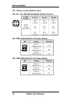
JP1: Factory use only (Default: open)
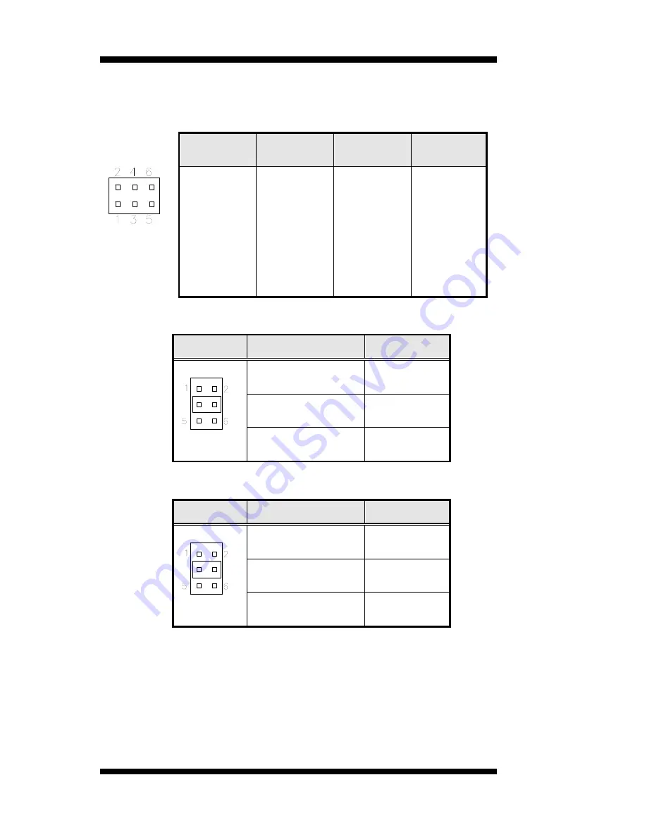
JP2, JP3, JP4: RS232/RS422/RS485 (COM1) Selection
COM1
Function
RS-232
RS-422
RS-485
Jumper
Setting
(pin closed)
JP2:
3-5&4-6
JP3:
1-2
JP4:
3-5 & 4-6
JP2:
1-3&2-4
JP3:
3-4
JP4:
1-3 & 2-4
JP2:
1-3&2-4
JP3:
5-6
JP4:
1-3 & 2-4
JP5: COM1 RS232 RI/+5V/+12V Power Setting
JP5
Setting
Function
Pin 1-2
Short/Closed
+12V
Pin 3-4
Short/Closed
RI
Pin 5-6
Short/Closed
+5V
JP6: COM2 RS232 RI/+5V/+12V Power Setting
JP6
Setting
Function
Pin 1-2
Short/Closed
+12V
Pin 3-4
Short/Closed
RI
Pin 5-6
Short/Closed
+5V
Summary of Contents for MI961F
Page 1: ...MI961F Intel H61 Express Chipset Mini ITX Motherboard USER S MANUAL Version 1 0A...
Page 4: ...iv MI961F User s Manual This page is intentionally left blank...
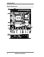
Page 8: ...INTRODUCTION 4 MI961F User s Manual Board Dimensions...
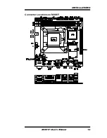
Page 17: ...INSTALLATIONS MI961F User s Manual 13 Connector Locations on MI961F...
Page 24: ...INSTALLATIONS 20 MI961F User s Manual This page is intentionally left blank...
Page 64: ...APPENDIX 60 MI961F User s Manual This page is intentionally left blank...


