background image

NR115 Motherboard 


2


On board EIDE: 


• 

2x PCI IDE ports supporting up to 4 devices  

• 

Support ATA-33/66/100, PIO up to mode 4 


On board I/O: 

• 

Low Pin Count (LPC) 3.3V interface between FWH and ICH2 

• 

2 serial ports - DB9 (16550 UART). 

• 

1 Parallel Port - DB25 with ECP/EPP support. 

• 

1 Floppy port with 1.2MB, 1.44MB and 2.88MB support.  

• 

1 PS/2 mouse connector, 1 PS/2 keyboard connector. 

• 

3 fan output headers. 

• 

4 USB Ports: 2 ports with RJ-45/USB connector in back panel, 2 ports with 2X5 header for 
front panel connection. 


 BIOS: 

• 

Plug & Play BIOS (AMI). 

• 

2Mb Firmware Hub 

• 

ACPI v2.0 – WfM 2.0 – SMBIOS v2.3 – DMI v2.1 – PC2001. 

• 

Auto detect for: CPU Speed – AGP 4X – ATA-100. 

• 

Wake-on PS/2 (KB, Mouse) & USB devices. 

• 

Rapid Boot support 

• 

WOL, ASF support 

• 

Power management: ACPI S3, S4 support


Additional Features: 

• 

Case intrusion header 

• 

Thermal sensor & CPU monitoring. 

• 

NIC with integrated MBA boot (complete WOL support) 

• 

BIOS recovery & Boot-Block overwrite via jumper. 

• 

Hardware Monitor Capability (SMSC LPC47M192). 

• 

Optional On Board LAN 


Expansion Slots: 

• 

1 AGP Slot (2X/4X mode). 

• 

3 PCI Slots (including 1 shared PCI/CNR Slot) 


Other: 

• 

Front panel I/O 2X9 header, key pin 14.  

• 

On-board buzzer. 


Summary of Contents for NR115

Page 1: ...NR115 Intel 845 Motherboard USER S MANUAL Intel Pentium 4 Processor Motherboard Rev 1 0...

Page 2: ...ard user s manual Item Checklist 1 NR115 Motherboard 1 Floppy Cable 1 ATA Cable 66 100 1 I O Shield 1 Heatsink Retention Module 1 CD for Motherboard Driver NR115 User Manual Quick Installation Guide I...

Page 3: ...wrist strap before handling computer components If one is not available touch both of your your hands to a safely grounded object or to a metal object 3 Place components on a level grounded antistatic...

Page 4: ...ply Cable 10 I O Back Panel Introduction 11 Jumpers Introduction 13 Chapter 3 AMI BIOS Setup 16 Entering Setup 16 The Main Menu 16 Standard CMOS Setup 17 Advanced CMOS Setup 18 Advanced Chipset Setup...

Page 5: ...uspend to RAM sleep state ACPI S3 Core Logic Chipset Intel i845 MCH Memory Controller Hub in 593 ball FC BGA package Intel 82801BA ICH2 I O Controller Hub 2 in 360 ball EBGA package Intel 82802AB 2 Mb...

Page 6: ...h 2X5 header for front panel connection BIOS Plug Play BIOS AMI 2Mb Firmware Hub ACPI v2 0 WfM 2 0 SMBIOS v2 3 DMI v2 1 PC2001 Auto detect for CPU Speed AGP 4X ATA 100 Wake on PS 2 KB Mouse USB device...

Page 7: ...I O Description 1 HD_PWR O Hard Disk LED pull up to VCC 2 HDR_BLNK_GRN O Front panel Green LED signal 3 HDA O Hard Disk Active LED signal 4 HDR_BLNK_YEL O Front panel Yellow LED signal 5 GND Ground 6...

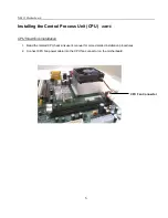
Page 8: ...such that the marked corner pin1 matches the corner near the base of the lever 3 Place the CPU into the socket If the CPU is unable to insert properly check its orientation and attempt to re install...

Page 9: ...ntral Process Unit CPU cont CPU Heat Sink Installation 1 Read the related CPU heat sink user s manual for more detailed installation procedures 2 Connect CPU fan power cable into the CPU fan connector...

Page 10: ...lock in the module 4 Repeat installation process when adding additional modules Total Memory Sizes With Unbuffered DDR DIMM Devices used on DIMM 1 DIMMx64 x72 2 DIMMsx64 x72 64 Mbit 2Mx8x4 banks 128 M...

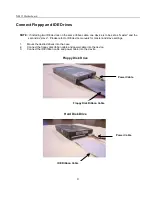
Page 11: ...de of the cable with the red stripe needs to be inserted into the Pin1 side of the floppy disk connector 2 Connecting the IDE ribbon cable into the motherboard The side of the cable with the red strip...

Page 12: ...cond as slave Please refer to IDE device manuals for master and slave settings 1 Mount the desired drives into the case 2 Connect the floppy disk ribbon cable and power cable into the device 3 Connect...

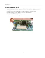
Page 13: ...serting the expansion card into the motherboard 2 Remove the slot covers from the chassis case where the expansion cards will be placed 3 Press the expansion card firmly into the expansion slot of the...

Page 14: ...E The ATX power connector is keyed for proper insertion 1 Place the plastic clip of the power connector over the plastic tab on the motherboard power connector The plastic clip should lock into the pl...

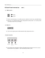
Page 15: ...and Serial Ports COM1 COM2 This connector supports 2 standard COM ports and 1 Parallel port Devices i e printer can be connected into the Parallel port Devices i e mouse and modem etc can be connected...

Page 16: ...OS supports the USB controller If not contact your OS or device s vendors for more information 4 Game Port This connector supports joystick MIDI keyboard and other related audio devices 5 Audio Connec...

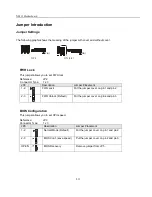
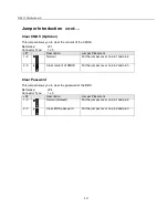
Page 17: ...x 3 JP2 Description Jumper Placement 1 2 FWH Lock Put the jumper cover on pin1 and pin2 2 3 FWH Unlock Default Put the jumper cover on pin2 and pin3 BIOS Configuration This jumper allows you to set CP...

Page 18: ...lacement 1 2 Normal Put the jumper cover on pin1 and pin2 2 3 Clear content of CMOS Put the jumper cover on pin2 and pin3 Clear Password This jumper allows you to clear the password of the BIOS Refere...

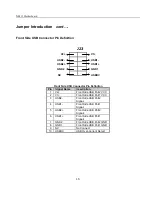
Page 19: ...1 V2 Front Side USB Port2 VCC 2 V1 Front Side USB Port1 VCC 3 USB2 Front Side USB Port2 Signal 4 USB1 Front Side USB Port1 Signal 5 USB2 Front Side USB Port2 Signal 6 USB1 Front Side USB Port1 Signal...

Page 20: ...to accept or enter the sub menu AMI HIFLEX SETUP UTILITY VERSION 1 38 2001 AMERICAN MEGATRENDS INC ALL RIGHTS RESERVED NR115 BIOS Rev 1 11 Standard CMOS Features Advanced CMOS Features Advanced Chipse...

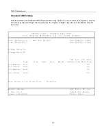
Page 21: ...Date mm dd yyyy Wed Nov 28 2001 Base Memory 639KB Time hh mm ss Extd Memory 127MB Floppy Drive A Floppy Drive B LBA BLK PIO 32Bit Type Size Cyln Head Wpcom Se Mode Mode Mode Mode Pri Master Auto On Pr...

Page 22: ...oot Devices Yes Intitial Display Mode Silent Display Mode at Add On Rom Init Force BIOS S M A R T for Hard Disk Disabled BootUp Num Lock On Floppy Drive Seek Disabled Primary Display VGA EGA Password...

Page 23: ...select the desired option for each item SDRAM Idle Timer Infinite Available Options SDRAM Read Thermal Management Disabled DRAM Integrity Mode Disabled Memory Hole Disabled AGP Aperture Size 64MB USB...

Page 24: ...ilable Options Re Call VGA BIOS at S3 Resuming Disabled Power Management APM Enabled Video Power Down Mode Suspend Hard Disk Power Down Mode Standby Suspend Time Out Minute Disabled Throttle Slow Cloc...

Page 25: ...select the desired option for each item AMIBIOS SETUP PCI PLUG AND PLAY SETUP 2001 AMERICAN MEGATRENDS INC ALL RIGHTS RESERVED Plug and Play Aware O S No Available Options Clear NVRAM No PCI Latency T...

Page 26: ...RIGHTS RESERVED OnBoard IDE Both Available Options OnBoard LAN Enabled LAN Chip Boot Rom Disabled OnBoard AC 97 Auto OnBoard FDC Auto OnBoard Serial PortA Auto OnBoard Serial PortB Auto Serial PortB M...

Page 27: ...tion for each item AMIBIOS SETUP HARDWARE MONITOR SETUP 2001 AMERICAN MEGATRENDS INC ALL RIGHTS RESERVED CPU Ratio Selection 15 0x Available Options System Hardware Monitor Chassis Intrusion Enabled C...

Page 28: ...AMIBIOS SETUP STANDARD CMOS SETUP 2001 AMERICAN MEGATRENDS INC ALL RIGHTS RESERVED Date mm dd yyyy Wed Nov 28 2001 Base Memory 639KB Time hh mm ss Extd Memory 127MB Floppy Drive A Floppy Drive B LBA B...

Page 29: ...AN MEGATRENDS INC ALL RIGHTS RESERVED NR115 BIOS Rev 1 11 Standard CMOS Features Advanced CMOS Features Advanced Chipset Features Power Management Setup PCI Plug and Play Setup Peripheral Setup Hardwa...

Page 30: ...MEGATRENDS INC ALL RIGHTS RESERVED NR115 BIOS Rev 1 11 Standard CMOS Features Advanced CMOS Features Advanced Chipset Features Power Management Setup PCI Plug and Play Setup Peripheral Setup Hardware...

Page 31: ...MEGATRENDS INC ALL RIGHTS RESERVED NR115 BIOS Rev 1 11 Standard CMOS Features Advanced CMOS Features Advanced Chipset Features Power Management Setup PCI Plug and Play Setup Peripheral Setup Hardware...

Page 32: ...2001 AMERICAN MEGATRENDS INC ALL RIGHTS RESERVED NR115 BIOS Rev 1 11 Standard CMOS Features Advanced CMOS Features Advanced Chipset Features Power Management Setup PCI Plug and Play Setup Peripheral...

Page 33: ...NC ALL RIGHTS RESERVED NR115 BIOS Rev 1 11 Standard CMOS Features Advanced CMOS Features Advanced Chipset Features Power Management Setup PCI Plug and Play Setup Peripheral Setup Hardware Monitor Setu...

Page 34: ...TRENDS INC ALL RIGHTS RESERVED NR115 BIOS Rev 1 11 Standard CMOS Features Advanced CMOS Features Advanced Chipset Features Power Management Setup PCI Plug and Play Setup Peripheral Setup Hardware Moni...

Page 35: ...NR115 Motherboard 31 NOTES...

Reviews: