American Megatrends, Inc., Olympus III User’s Guide (Series 875)
28
Step 5 Attach Internal Cables,
Continued
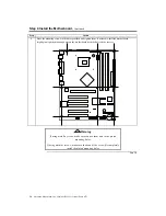
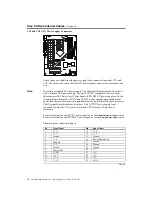
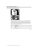
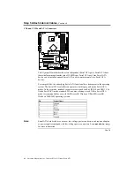
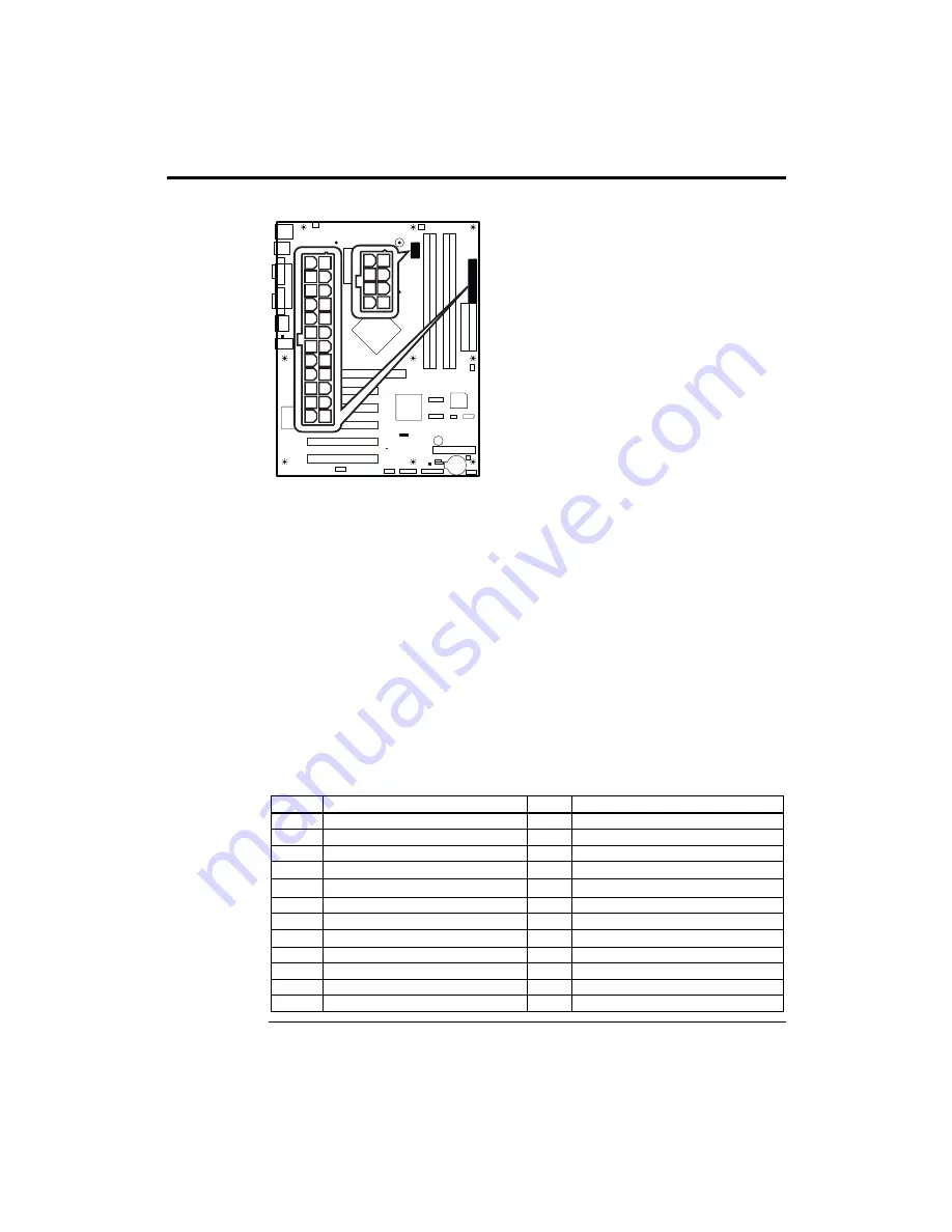
CN1 and CN2 ATX Power Supply Connectors
CN1
CN2
Attach the power cables from the power supply to the connectors located at CN1 and
CN2. The socket is keyed so that the ATX power supply connector can only mount one
way.
Note:
Do not use a standard ATX power supply. The Olympus III motherboard will not boot
with a standard ATX power supply. Use only ATX12V-compliant or Server System
Infrastructure (SSI) Entry-Level Power Supply (EPS) EPS12V power supplies with the
Olympus III motherboard. ATX12V and EPS12V power supplies have an additional
power lead that provides required supplemental power for the Intel Pentium 4 processor.
The Olympus III motherboard will not boot if the ATX12V power supply is not
connected to both the CN1 4-pin (or 8-pin) and CN2 20-pin (or 24-pin) power
connectors.
For more information on ATX12V power supplies, see the
formfactor.org
website.
For more information on SSI EPS12V power supplies, see the
ssiforum.org
website.
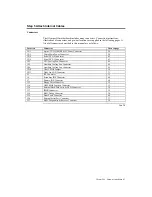
The main power connector pinout is:
Pin Signal
Name
Pin Signal
Name
1
3.3 V
13
3.3 V
2
3.3 V
14
-12 V
3 Ground
15
Ground
4 +5
V
16
Power Supply On
5
Ground
17 Ground
6 +5
V
18
Ground
7 Ground
19
Ground
8
Power OK
20 -5
V
9
5 VSB
21
+5 V
10
+12 V
22
+5 V
11
+12 V
23
+5 V
12 +3.3
V
24 GND
Cont’d
Summary of Contents for Olympus III
Page 1: ...Olympus III User s Guide MAN 875 02 02 04...
Page 14: ...American Megatrends Inc Olympus III User s Guide Series 875 4 Rear I O Ports...
Page 20: ...American Megatrends Inc Olympus III User s Guide Series 875 10...
Page 138: ...American Megatrends Inc Olympus III User s Guide Series 875 128...
Page 140: ...American Megatrends Inc Olympus III User s Guide Series 875 130...
Page 146: ...American Megatrends Inc Olympus III User s Guide Series 875 136...

