11
5800 SE 78th St. Ocala, FL 34472
AP20BCF200-3-XL Installation & Operations Manual
P: (800) 327-3015
E: Service@americanpanel.com
Step
Description
Diagram
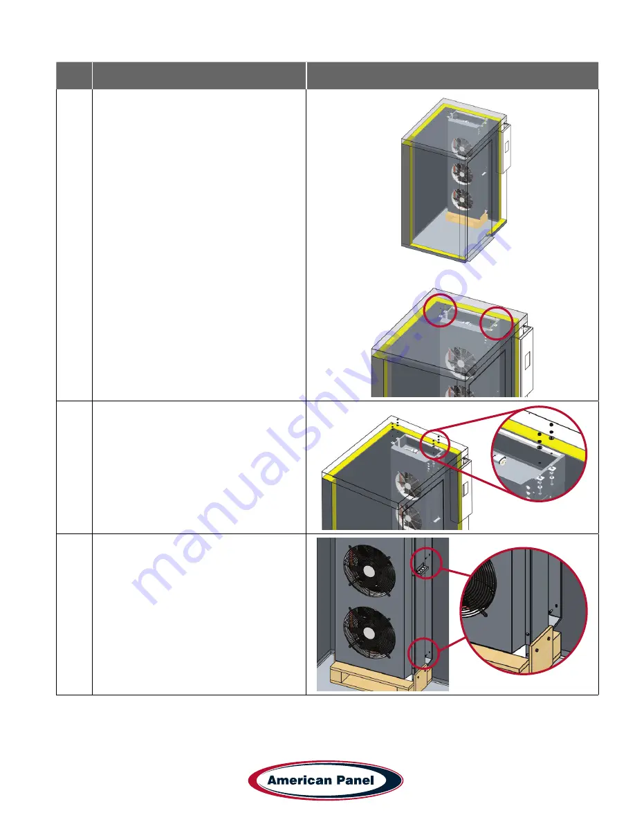
6
Position the evaporator assembly along the
side wall, behind the side of the door with
the controller. Align the top bracket slots to
the mounting holes in the ceiling panel.
7
Secure the evaporator to the ceiling panel
using the provided hardware – 3/8” bolts,
flat washers, split washers, and nuts. See
hardware bag labeled “Evaporator Assembly
Fasteners”. Care should be taken when
tightening the screws. Tighten each screw
one turn at a time in a diagonal pattern to
avoid damaging the screws.
8
Secure the evaporator assembly to the
back wall using the provided 10-24 hex
head washer screws located inside the bag
labeled “Evaporator Assembly Fasteners”.


