background image


13 


14.5


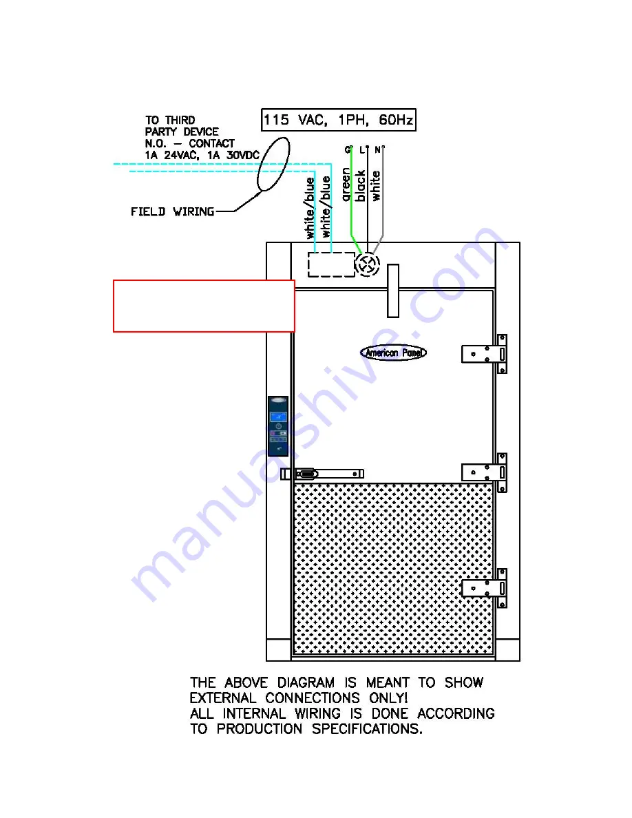
Alarm Dry Contact 

Low voltage white with blue stipe wires are located inside the rectangular junction box, next to the vapor proof light fixture.  


ELECTRICIAN MUST 

SEAL THE CONDUIT AT 

BOTH ENDS! 

Summary of Contents for IC+

Page 1: ...lligent Control and Alarm System Cooler is Better TM American Panel Corporation 5800 S E 78th Street Ocala Florida 34472 3412 Phone 352 245 7055 Fax 352 245 0726 E mail service americanpanel com Rev 5 11 2020 ...

Page 2: ...l will ensure you years of trouble free operation On occasion situations can arise and will require the help of the factory whether it be technical information service or replacement of parts We have a highly trained Customer Service and Parts Department available to help when these situations arise We also offer a national network of service agencies that may be contacted for warranty and out of ...

Page 3: ...f 4 8 HACCP Recording 4 9 Wi Fi Connectivity and Remote Notification 4 10 User Interface 7 11 Navigating the Menu 8 12 Restore the Default Settings 8 13 Troubleshooting 8 14 Field Wiring 9 14 1 Main Power 9 14 2 Field Mounted Light Fixture 10 14 3 PANIC BUTTON FOR PARTITION DOOR 11 14 4 3 WAY 4 WAY Configuration and Remote Light Button 12 14 5 Alarm Dry Contact 13 14 6 Evaporator Fan Cut Out Switc...

Page 4: ...ver the temperature probe To monitor the air temperature at a different location an extended temperature probe is available for purchase If equipped with an extra temperature probe IC will monitor the temperature at two locations or the temperature of two different cabinets One probe display Two probes display 3 Temperature Alarms If the temperature inside the walk in cabinet goes above the high a...

Page 5: ... on the IC 5 Door Open Alarm IC controllers monitor the status of the door If the door is not fully closed or if left open for more than the pre set time 5 minutes by default the IC controller will display the alarm message and the onboard buzzer will sound If IC is connected to the local WiFi network it will send an alarm message via e mail Close the door to reset the alarm 6 Door Frame Heater an...

Page 6: ...he HACCP data can be previewed on the IC display To do so push the MENU button and go to HACCP Preview Preview Events select any of the events in the list to view the details related to that event To download the data via USB insert a USB drive in the USB port and follow the prompts on the display If IC controller is connected to an internet enabled Wi Fi network it can be setup to send periodic e...

Page 7: ...lity of the generic account icpluswalkin gmail com and it reserves the right to modify or discontinue the account without advance notice 8 Outgoing Email Server Setup In the Select outgoing email choose one of the available options fill in the required information and press Save Changes when done Available options Default select this option if you choose to keep the generic email account provided ...

Page 8: ...by the email domain corresponding to the cellphone carrier For example to receive texts on a T Mobile number 123 456 7890 enter 1234567890 tmomail net To find out the email domain for your specific carrier search on the internet for Email to text gateway list or contact your cellphone carrier 14 Internet Wi Fi Setup Choose a Wi Fi network from the list enter the password and press connect 10 Press...

Page 9: ...ICON INDICATING THAT THE LIGHT INSIDE THE CABINET IS ON STEADY WI FI ICON INDICATES THAT THE CONTROLLER IS CONNECTED TO THE LOCAL NETWORK UNIT OF MEASURE o F INDICATES DEGREES FAHRENHEIT WALK IN CABINET TYPE USB PORT LIGHT BUTTON ALARM MUTE BUTTON MENU NAVIGATION BUTTONS ...

Page 10: ...d and check the temperature after few minutes to make sure it goes back to the normal range The IC beeps and displays the high temperature alarm message If the high air alarm went off the temperature inside the cabinet is above the preset limit The flashing number is the measured temperature inside the cabinet To silence the alarm press the alarm mute button Check all doors to be closed check the ...

Page 11: ...t see electrical schematic at chapter 14 3 in this document Blue 1 ea and Yellow 1 ea 3 WAY Multi Way configuration wires terminated inside the vapor proof light fixture or stubbed out see electrical schematic at chapter 14 4 of this document White with blue stripe 2 ea alarm dry contact wires terminated in the rectangular connection box located next to the vapor proof light fixture or stubbed out...

Page 12: ...10 14 2 Field Mounted Light Fixture ELECTRICIAN MUST SEAL THE CONDUIT AT BOTH ENDS ...

Page 13: ...11 14 3 PANIC BUTTON FOR PARTITION DOOR ELECTRICIAN MUST SEAL THE CONDUIT AT BOTH ENDS ...

Page 14: ...AY Configuration and Remote Light Button This configuration is typical to cabinets that have multiple doors The user will be able to turn on and off the light from any door ELECTRICIAN MUST SEAL THE CONDUIT AT BOTH ENDS ...

Page 15: ...13 14 5 Alarm Dry Contact Low voltage white with blue stipe wires are located inside the rectangular junction box next to the vapor proof light fixture ELECTRICIAN MUST SEAL THE CONDUIT AT BOTH ENDS ...

Page 16: ...14 14 6 Evaporator Fan Cut Out Switch The pink wires are located inside the rectangular connection box next to the vapor proof light fixture ELECTRICIAN MUST SEAL THE CONDUIT AT BOTH ENDS ...

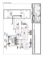
Page 17: ...15 15 Electrical Schematic ...

Page 18: ...American Panel Corporation 5800 S E 78th Street Ocala Florida 34472 3412 Phone 352 245 7055 Fax 352 245 0726 E mail service americanpanel com ...

Reviews: