background image

Pub. No. 11-AC14D1-6

02/08

Technical Literature - Printed in U.S.A.

American Standard Heating & Air Conditioning

Troup Highway
Tyler, TX 75707-9010

Summary of Contents for 2A7A8

Page 1: ... sion number 3 The support pad must NOT be in direct contact with any structure Unit must be positioned a minimum of 12 from any wall or surrounding shrubbery to insure adequate airflow Clear ance must be provided in front of control box access panels any other side requiring service access to meet National Electrical Code Also the unit location must be far enough away from any structure to preven...

Page 2: ...The liquid line valve is not a back seating valve see WARNING at top of next column WARNING Extreme caution should be ex ercised when opening the Liquid and Gas Line Service Valves Turn valve stem counterclockwise only until the stem contacts the rolled edge See Figures 3 and 5 No torque is required Failure to follow this warning will result in abrupt release of system charge and may result in per...

Page 3: ...al conduit whenever vibration trans mission may create a noise problem within the structure 6 The use of color coded low voltage wire is recommended to simplify connections between the outdoor unit the AccuLink control and the indoor unit Table 1 NEC Class II Wiring NOTE The maximum total cable length for the entire Comfort Control communicating system is 500 ft 18 AWG 7 Mount the AccuLink control...

Page 4: ... R E S T R IC T E D I D A IR F L O W R E F C IR C U IT R E S T R IC T IO N S O D F A N S P E E D S W IT C H TROUBLESHOOTING CHART WHAT TO CHECK B BK Y2 Y1 O R D W1 W3 G W2 B D B R D X2 Y2 Y1 O AccuLink COMFORT CONTROL 24VAC HOT 24VAC Common DATA AccuLink INDOOR UNIT AccuLink OUTDOOR UNIT FIELD WIRING DIAGRAM COMMUNICATING INDOOR UNIT COMMUNICATING OUTDOOR UNIT 6 main disconnect switch This will ac...

Page 5: ... If the system charge is correct the CHARGED LED will turn on and remain on for one 1 hour Once charged the system will exit Charge Assist and control will return to the Comfort Control If the system charge is low the ADD LED will turn on and stay on up to one 1 hour or until enough refrigerant is added to reach the required system charge level and turn on the CHARGED LED When the ADD LED is on th...

Page 6: ...1 1045 41 1 8 946 37 1 4 870 34 1 4 7 8 3 8 152 6 98 3 7 8 219 8 5 8 86 3 3 8 711 28 2A7A8036C 4 1 1045 41 1 8 946 37 1 4 870 34 1 4 7 8 3 8 152 6 98 3 7 8 219 8 5 8 86 3 3 8 711 28 2A7A8048C 4 1 1045 41 1 8 946 37 1 4 870 34 1 4 1 1 8 3 8 152 6 98 3 7 8 219 8 5 8 86 3 3 8 711 28 2A7A8060C 4 1 1045 41 1 8 946 37 1 4 870 34 1 4 1 1 8 3 8 152 6 98 3 7 8 219 8 5 8 86 3 3 8 711 28 ...

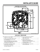
Page 7: ...Fittings properly insulated 3 Have all Refrigerant Lines been secured and isolated properly 4 Have passages through masonry been sealed If mortar is used prevent mortar from coming into direct contact with copper tubing 5 Verify tightness of all electrical connects 6 Observe outdoor fan during on cycle for clearance and smooth operation 7 Indoor coil drain line drains freely Pour water into drain ...

Page 8: ...Pub No 11 AC14D1 6 02 08 Technical Literature Printed in U S A American Standard Heating Air Conditioning Troup Highway Tyler TX 75707 9010 ...

Reviews: